Inspection and Installation
2.7.4 GPIB Interface
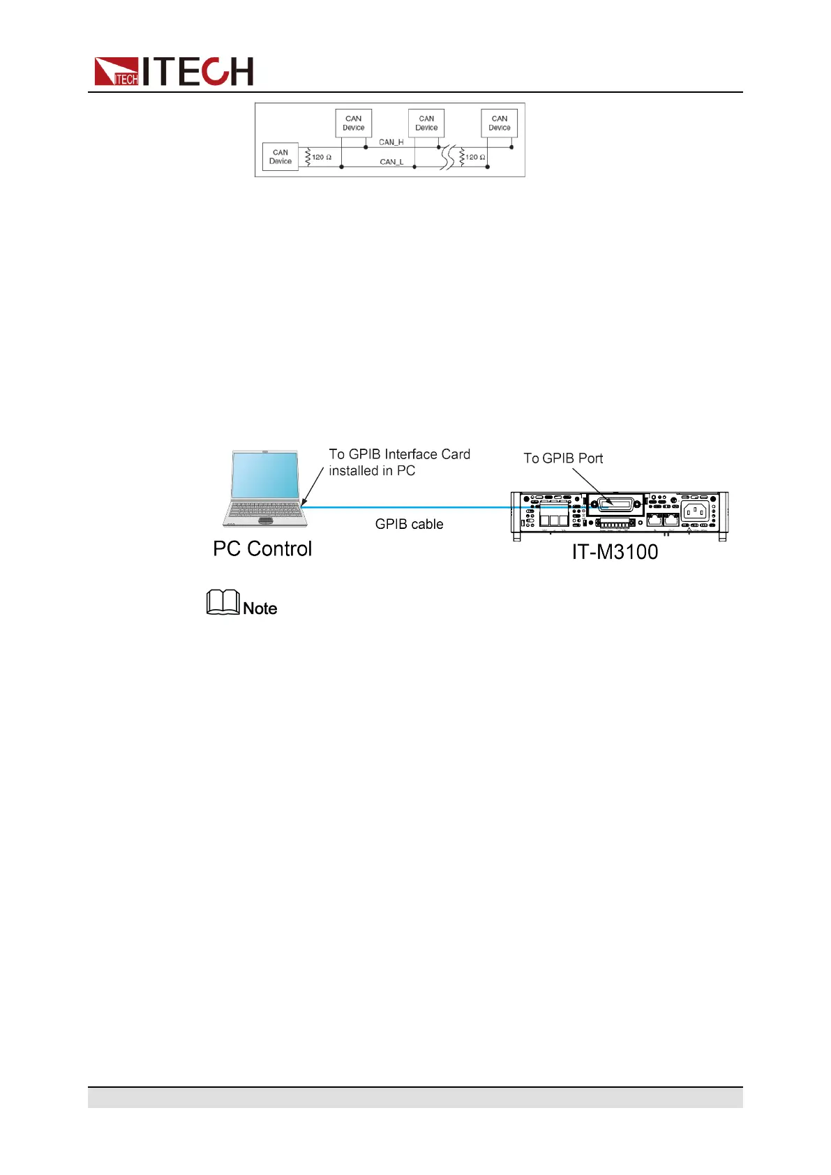
When the optional interface card is a GPIB interface (IT-E1205), you need to
know the following.
Each device on the GPIB (IEEE-488) interface must have a unique whole num-
ber address between 0 and 30. Your computer’s GPIB interface card address
must not conflict with any instrument on the interface bus. This setting is non-
volatile; it will not be changed by power cycling or *RST. The figure below shows
a typical GPIB interface system.
The rear panel shown in the figure is only an example. The actual appear-
ance of the rear panel is subject to the specific instrument.
You can change the GPIB address in the system menu. The operation steps are
as follows.
1. Refer to the GPIB connection diagram, Connect the power supply and the
computer using a IEEE-488 bus.
2. Set the GPIB address in the system menu.
a. Press [Shift]+[Display] (System) to enter into the system menu
interface.
b. Use left and right keys or rotate the knob to select Comm and press
[Enter] key to confirm.
c. Use left and right keys or rotate the knob to select GPIB and press
[Enter] key to confirm.
d. Rotate the knob to adjust the GPIB address and press [Enter] key to
confirm.
e. After finishing the setting, press [Esc] to exit.
Copyright © Itech Electronic Co., Ltd.
34