Functions and Features
• Keypad: Select the front panel [Shift]+[On/Off] (Trigger) button as the trig-
ger source;
• Bus: Select the remote interface command as the trigger source, such as
the *TRG command;
• Ext: Select the rear panel trigger signal interface TRIG± (IN status) as the
trigger source. Please refer to 4.2.4 Set the TRIG± Interface Status (Ext IO)
for detailed information about TRIG± interface status settings.
The procedures to set the menu item are as follows.
1. Press [Shift]+[V-set] (Config) to enter into the configuration menu interface.
2. Use left and right keys or rotate the knob to select Trig Source and press
[Enter] key to make the parameter in modification.
3. Rotate the knob to adjust the parameter.
4. After setting, press [Enter] key to confirm.
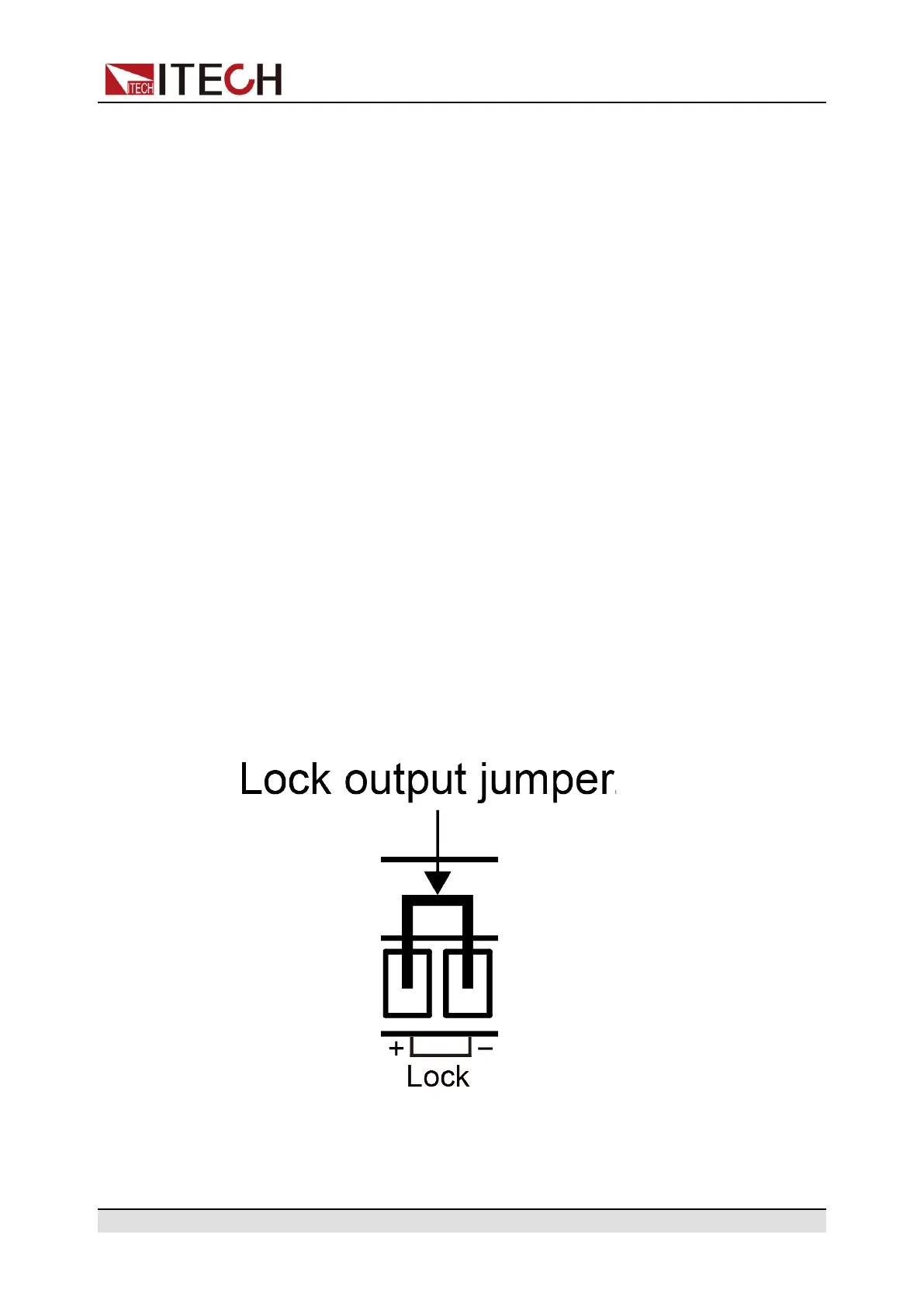
4.1.6 Output Lock Control
The IT-M3100D series power supply rear panel provides an output lock inter-
face Lock±. The user can disable the power output by shorting the Lock+ and
Lock– interfaces to prevent the from mishandling the power supply during the
test and causing damage to the DUT. The output can be re-enabled by remov-
ing the jumper or shorting clip between the Lock+ and Lock– connectors.
The figure below shows the short connection between the Lock± interfaces.
Copyright © Itech Electronic Co., Ltd.
47