Inspection and Installation
Name Description
Baud rate Select the baud rate from the following op-
tions: 20k, 40k, 50k, 80k, 100k, 125k, 150k,
200k, 250k, 400k, 500k, 1000k.
Instrument Address Range: 1 to 127
The operation steps are as follows.
1. Press [Shift]+[Display] (System) to enter into the system menu interface.
2. Use left and right keys or rotate the knob to select Comm and press [Enter]
key to confirm.
3. Use left and right keys or rotate the knob to select CAN and press [Enter]
key to confirm.
4. Use left and right keys or rotate the knob to select Baud rate and press
[Enter] key to confirm.
5. Rotate the knob to set the baud rate and press [Enter] key to confirm.
6. Use left and right keys or rotate the knob to select Address and press
[Enter] key to confirm.
7. Rotate the knob to set the communication address and press [Enter] key to
confirm.
8. After finishing the setting, press [Esc] to exit.
CAN Troubleshooting
If you meet some problems when communicating with PC by CAN interface,
please check the following items:
• PC and power supply must have the same baud rate.
• Ensure you have used the correct communication cable (CAN_H, CAN_L).
Please pay attention that some cable may not have a correct internal wiring
even it is with an appropriate interface.
• The interface cable is correctly connected (CAN_H to CAN_H, CAN_L to
CAN_L)
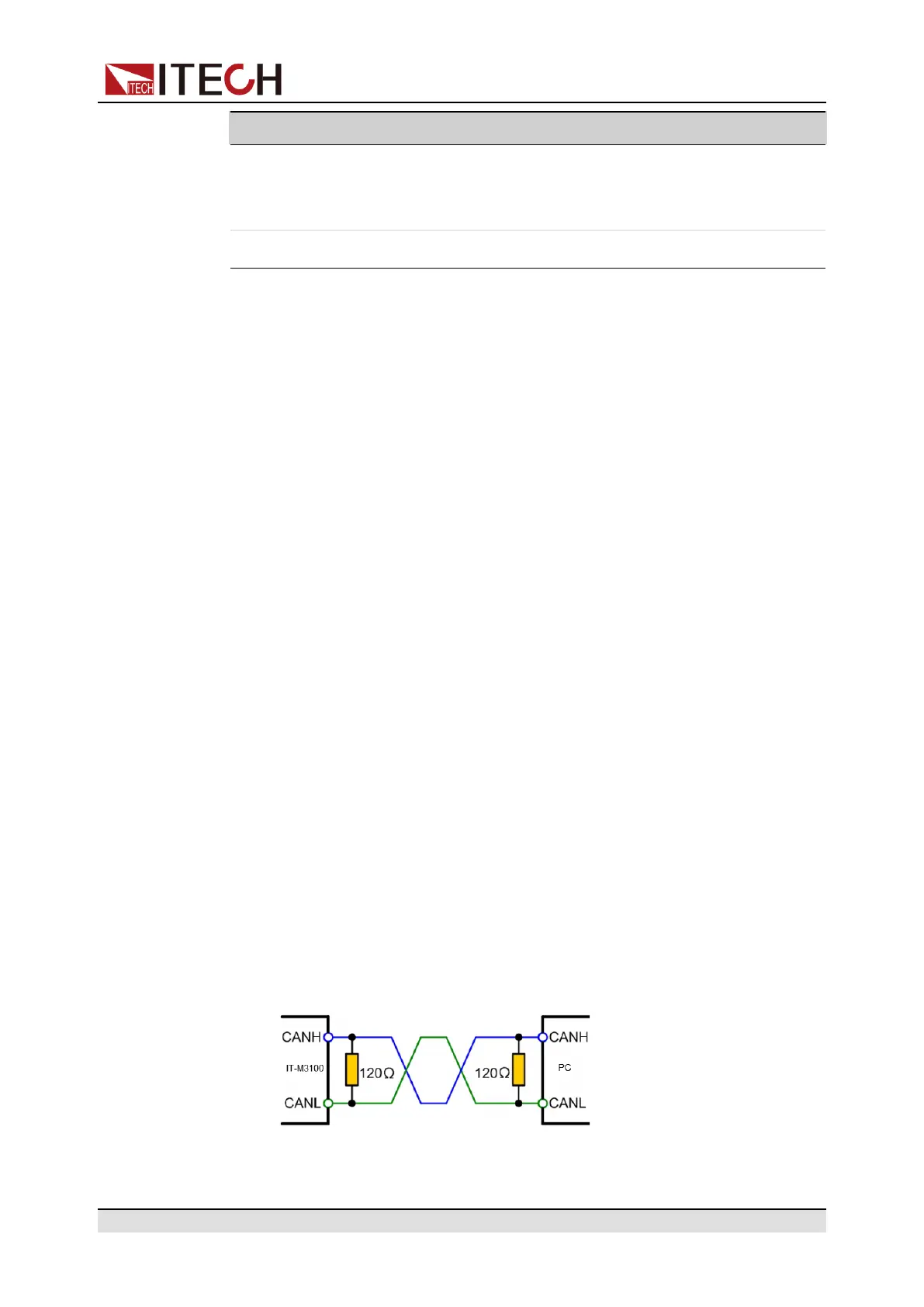
• If the communication signal is poor or unstable, it is recommended to con-
nect a 120 Ω terminating resistance.
– The connection diagram of a single device is as below.
– The connection diagram of multiple devices is as below.
Copyright © Itech Electronic Co., Ltd.
33