Basic Operation
In this chapter, all the pulse signals involved in the digital I/O function are
switched from high level to low level.
General Digital I/O Function
• Signal definition
Digital I/O functions involve input and output levels and pulse signals. The in-
put signal is the control signal provided externally to IT-M3900C, the output
signal is the level signal provided externally by IT-M3900C, and the pulse
signal is the edge signal switched between high and low levels.
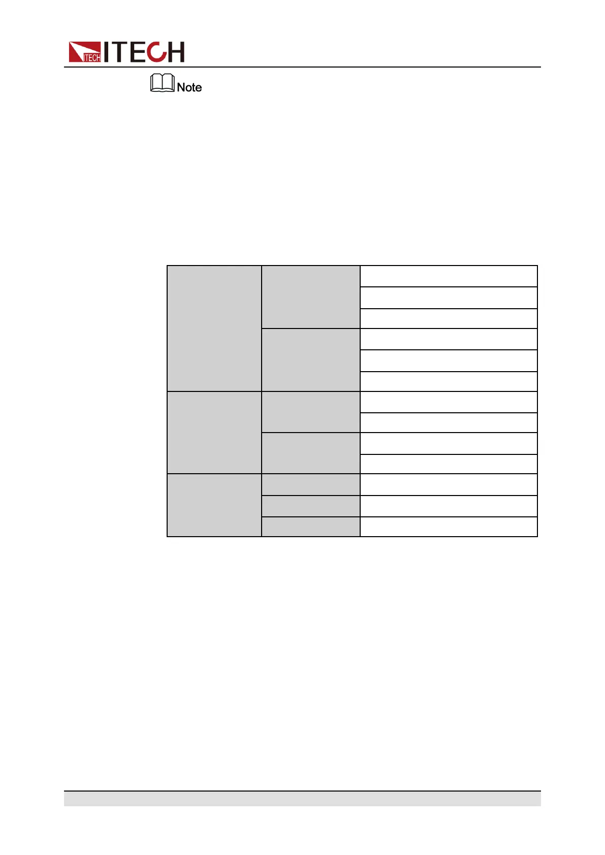
Input signal
High level signal
Typical: 5V
Range: 1.6V-15V
Current: ≤100mA
Low level signal
Typical: 0V
Range: -5V-0.8V
Current: ≤100mA
Output signal
High level signal
Voltage level: 5V
Current: ≤1mA
Low level signal
Voltage level: 0V
Current: 0.5mA
Pulse
Level rise slope
10us
Level fall slope
2us
Width 30us
• Input/Output Function
The IO-1 ~ IO-7 pins are featured default function, the user can setting the
function of pin according to requirement. The Input and Output are the gen-
eral digital I/O function, and the parameter settings and functions of the sev-
en pins are the same.
The IO-1~IO-7 pins provide default functions. Users can realize control ac-
cording to the functions defined. Users can also reset the input or output
properties of the present pin and customize the function use of the pin ac-
cording to their needs.
– When pins 1 to 7 are configured to Output function, either high level
(False) or low level (True) can be Output.
– When pins 1 to 7 are configured to Input function, an external signal can
be Input to this pin, and the instrument can detect the state of the exter-
nal signal.
Copyright © Itech Electronic Co., Ltd.
141