Power Supply Function
When the instrument is in Sense Reverse Protection state, you should check
whether the polarities are connected reversely or not firstly. If yes, you can re-
open the output after the polarities connect correctly.
The voltage difference between output terminal and remote sense terminal of
each model is not the same. When the remote sense terminal is connected re-
versely, the maximum voltage will not exceed the sum of output terminal voltage
and the difference voltage.
When Sense is reversed or short-circuited, the voltage meter value is dis-
played as a positive/negative value close to 0, and abnormal high voltage
output does not occur, which can avoid damage to the DUT.
4.6 Function Menu for Power Supply
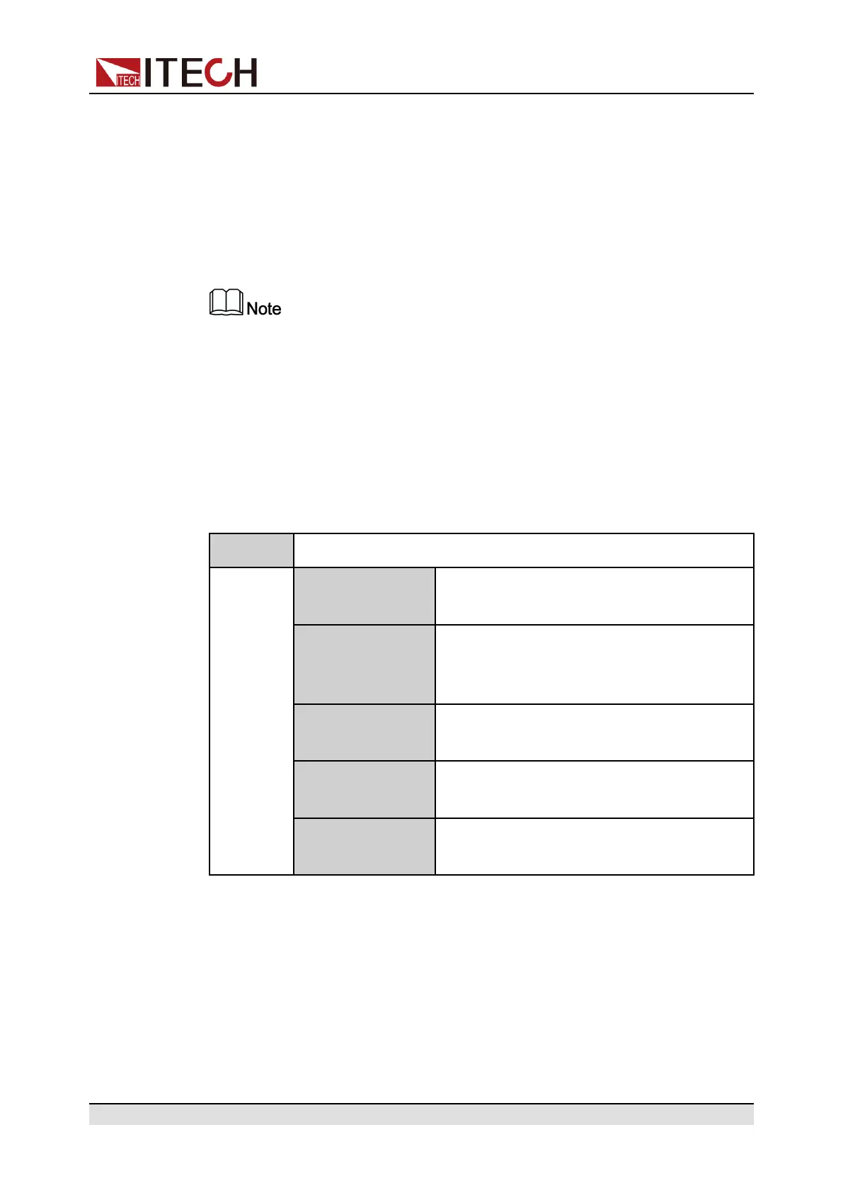
The Function menu of the power supply includes the following:
Function Function Menu for Power Supply
LIST LIST program editing, file import/export, pro-
gram running (see 4.6.1 LIST Function).
BATTERY Battery charging and discharging testing
function (see 4.6.2 Battery Charging/Dis-
charging Test Function).
Road-Vehicles Built-in waveform function (see 4.6.3 Built-in
Waveform Function).
SAS PV simulation function (see 4.6.4 Solar Pho-
tovoltaic Curve Simulation Function (SAS)).
Battery Emulator Battery simulation test function (see 4.6.5
Battery Simulation Function).
4.6.1 LIST Function
This series power supply supports a total of 10 List files (List01 to List10), each
of which can be set up to 200 steps. You need to edit the voltage/current value,
slope and time width of each step, or you can set repeat times (1 to 65535) for
Copyright © Itech Electronic Co., Ltd.
62
 Loading...


