Basic Operation
– Under the default condition (Not-Invert), when the pin (1 to 7) is config-
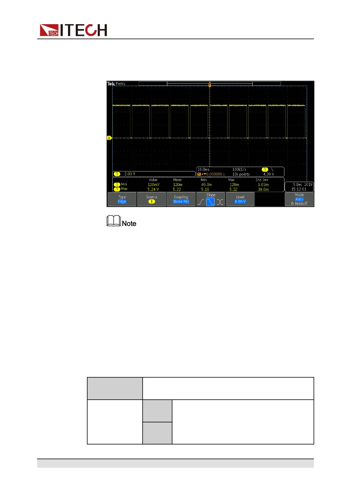
ured as Output→PWM, the user needs to set the frequency (PWM Freq)
and duty cycle (PWM Duty) values. For example, if the PWM Freq is set
to 100Hz and the PWM Duty is set to 10%, the output waveform is as
follows:
In the above figure, the peak voltage (minimum value) is 5.16V and
the cycle is 10ms. The high level duration is 9ms and the low level du-
ration is 1ms in one cycle.
• Signal Revert
Select Invert or not under the IO Settings menu. If setting to Not-Invert, it
means the default level will be valid. If setting to Invert, it means the valid sig-
nal is reversed. For example, the IO-5 pin is inhibit output by default and the
high level is valid, when select revert Invert, the low level is valid and the in-
strument output is disabled.
5.11.1 IO–1. Ps-Clear, Not-Invert
IO-1 pin can be set to 【Ps-Clear】, 【Input】, 【Output】.
Parameter Description
IO–1. Ps-Clear,
Not-Invert
Parameter setting for pin 1.
Not-
Invert
Indicates whether to invert the input/output
pulse or level signal.
• Invert: Yes
• Not-Invert: No
Invert
Copyright © Itech Electronic Co., Ltd.
142
 Loading...


