Basic Operation
d. According to step 2, set Mx and Mb of the corresponding pins.
4. Adjust the output of DC Power Supply 1 from -5V to 5V, and adjust the out-
put of DC Power Supply 2, DC Power Supply 3 from -10V to 10V.
The actual output voltage and current of the instrument will change accord-
ing to the following rules:
• Pin 8 controls the actual output voltage of the instrument from 0V to
500V.
• Pin 9, pin 10 monitor the actual output current of the instrument: When
the output current is higher than the upper limit I+ set by pin 9, the instru-
ment outputs the current at the value of I+; When the output current is
lower than the lower limit I- set by pin 10, the instrument outputs the cur-
rent at the value of I-.
5.13 View the System Information (System Info)
This menu item is used to view the system information of the instrument.
The procedures to view the system information are as follows.
1. Press the composite keys [Shift]+[P-set] (System) on the front panel to en-
ter the system menu.
2. Turn the knob to select the System Info and press [Enter].
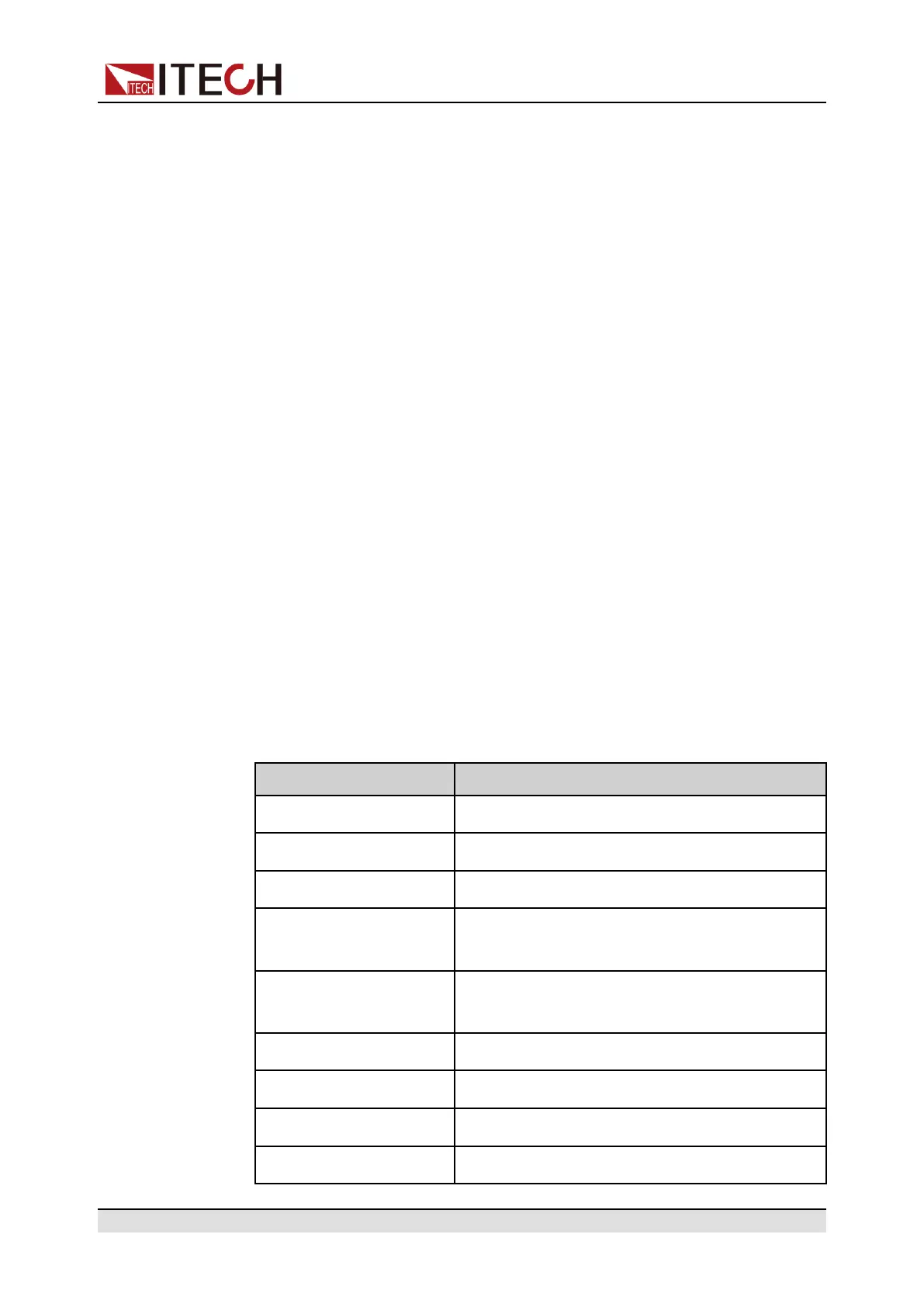
You can use knob to view the following system information.
Parameter Description
Model Display the instrument model.
SN Display the serial number.
Main Ver Display the system version information.
Ctrl1 Ver Display the version information of the control
panel 1.
Ctrl2 Ver Display the version information of the control
panel 2.
Date Display the system time.
Voltage Max Display the maximum voltage value.
Voltage Min Display the minimum voltage value.
Current Max Display the maximum current value.
Copyright © Itech Electronic Co., Ltd.
164
 Loading...


