Basic Operation
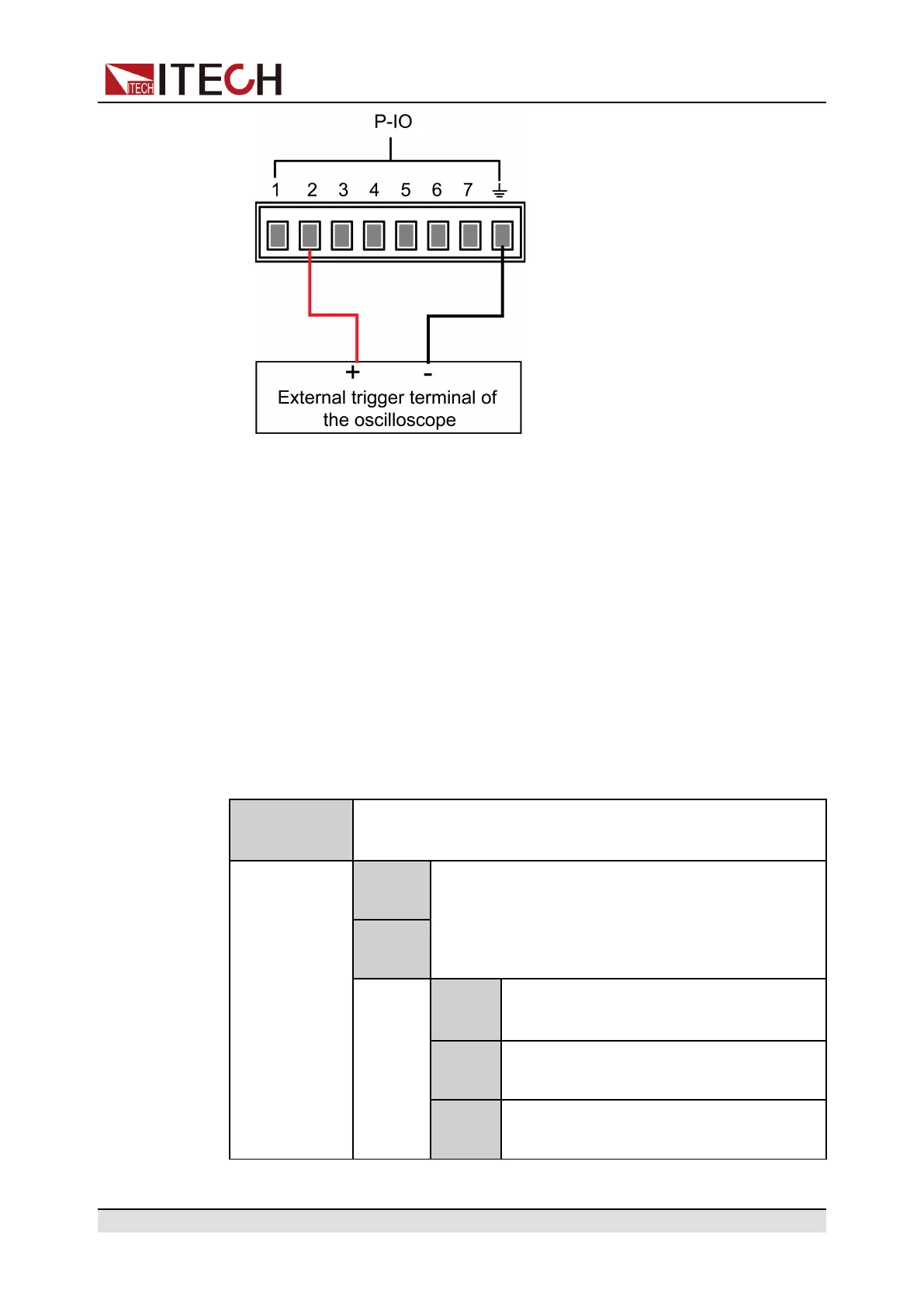
2. Confirm that pin 2 function is set to the default option, namely
IO-2. Ps, Not-Invert.
3. Taking OVP as an example, set the protection point of OVP.
4. Build the test environment to enable the instrument to enter the OVP state.
5. Check the oscilloscope and confirm that pin 2 outputs low level.
5.11.3 IO–3. Off-Status, Not-Invert
IO-3 pin can be set to 【Off-Status】, 【Input】, 【Output】.
Parameter Description
IO–3. Off-Sta-
tus, Not-Invert
Parameter setting for pin 3.
Not-
Invert
Indicates whether to invert the input/output pulse
or level signal.
• Invert: Yes
• Not-Invert: No
Invert
Off-
Status
This default function indicates the exist-
ing [On/Off] state of the instrument.
Input Pin 3 receives the level signal from the
outside.
Output Pin 3 sends the digital signal (1, 0, PWM)
to the outside.
Copyright © Itech Electronic Co., Ltd.
146
 Loading...


