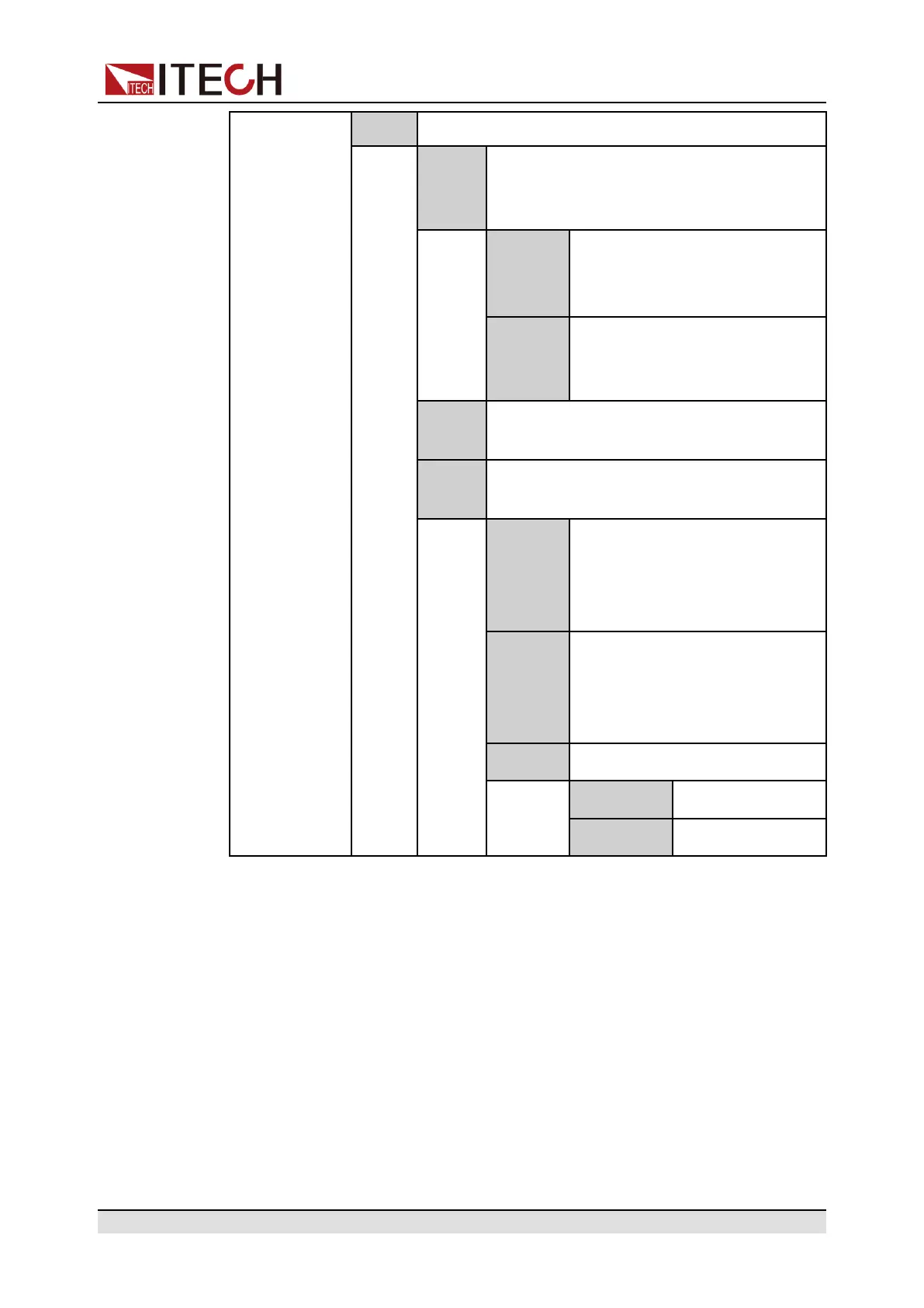
Basic Operation
• Not-Invert: No
Inhibit This default function means that pin 5 of
the P-IO controls the operation of the
instrument.
Living Select Living, and power supply
will be operated in the mode of
Living.
Latch Select Latch, and power supply
will be operated in the mode of
Latch.
Input Pin 5 receives the level signal from the
outside.
Output Pin 5 sends the digital signal (1, 0, PWM)
to the outside.
True By default (Not-Invert), the out-
put digital signal is 1 (i.e. low
level), and in the case of Invert,
the output is high level.
False By default (Not-Invert), the out-
put digital signal is 0 (i.e. high
level), and in the case of Invert,
the output is low level.
PWM Digital signal of PWM.
PWM Freq Frequency
PWM Duty Duty cycle
How to Use
• When pin 5 is set to Inhibit-Living (Not-Invert), pin 5 can control the instru-
ment’s output state based on the level signal from external input.
– Under default conditions (namely, pin 5 is not connected), the input is
high level, and it will not impact the instrument’s output state.
– When the [On/Off] is in On state, input low level to pin 5, and it will im-
pact the output state: The [On/Off] button light is lighted on and VFD still
displays On, but the actual output is 0; when pin 5 receives high level sig-
nal again, the output state is recovered.
Copyright © Itech Electronic Co., Ltd.
152
 Loading...


