Inspection and Installation
Copyright © Itech Electronic Co., Ltd. 13
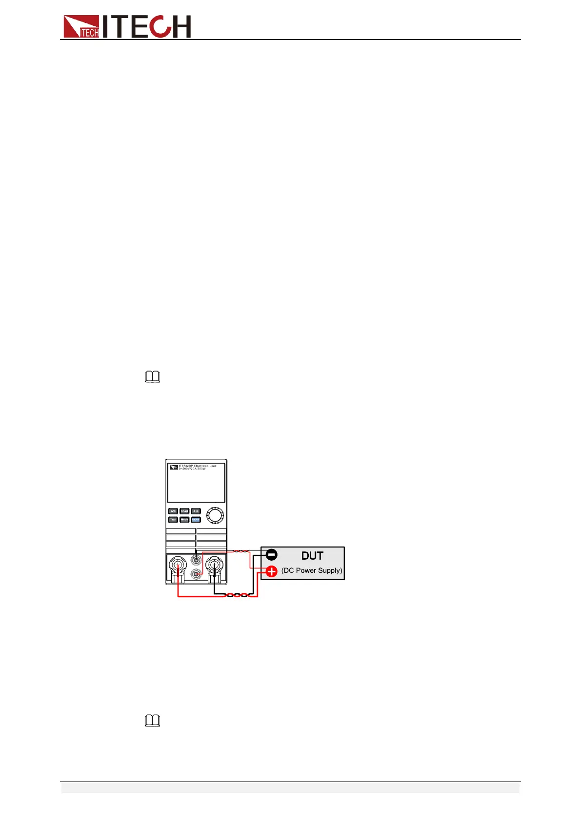
1. Before connecting the DUT, be sure that the Mainframe Power is in Off
position.
2. Remove the cover of input terminal.
3. Loosen the screws of the input terminals and connect the red and
black test cables to the input terminals. Re-tighten the screws.
4. Thread the red and black test cables through the input terminals cover
of the instrument and install the cover.
5. Directly connect the other end of the red and black cables to the DUT.
Connecting the DUT (Remote Sensing)
When load is at CV、CV or CR mode, lead length are relatively long or load
regulation is critical, or load consumes high-current, there will be voltage drop
in the leads connected between load and measured object which affect the
accuracy of measurement, then the sense connection can be applied. Fig 3-10
illustrates a typical connection between module and device for remote sense
operation.
Remote Sensing: Sense+ and Sense- are the remote sensing inputs. By
eliminating the effect of the inevitable voltage drop in the load leads, remote
sensing provides greater accuracy by allowing the load to regulate directly at
the source's output terminals. You should enable the remote sense function in
the configure menu and then connect the remote sense lines. The front panel of
the module shows “sense”.
Take single channel module for example, there’re two input connectors. One is
load input measurement terminal; the other is Vsense measurement terminal.
Note
The electric potential on the positive terminal of Vsense connector must be higher than
negative one.
The connection diagram and steps of remote sensing are as follows:
⚫ Front panel terminal wiring
1. Before connecting the DUT, be sure that the Mainframe Power is in Off
position.
2. Use armored twisted-pair cables to connect the remote sense
terminals and the equipment under test.
3. Loosen the screws of the input terminals and connect the red and
black test cables to the input terminals. Re-tighten the screws.
4. Connect the other end of the remote sense cables and the red and
black cables to the DUT.
Note
Only the IT8731P/IT8732P/IT8732BP/IT8733P/IT8733BP/IT8722P/IT8723P/IT8722BP
modules support front panel terminal wiring.
⚫ Rear panel terminal wiring