Inspection and Installation
Copyright © Itech Electronic Co., Ltd. 14
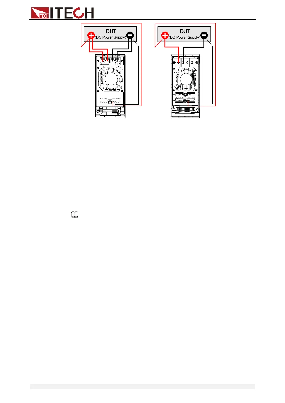
(Single channel modules) (Double channel modules)
1. Before connecting the DUT, be sure that the Mainframe Power is in Off
position.
2. Remove the cover of input terminal.
3. Loosen the screws of the input terminals and connect the red and
black test cables to the input terminals. Re-tighten the screws.
4. Use armored twisted-pair cables to connect the remote sense
terminals and the equipment under test.
5. Install the terminal cover, leave the other end of remote sense cables
and the red and black cables outside.
6. Connect the other end of the remote sense cables and the red and
black cables to the DUT.
Note
For safety requirements, load wires between the electronic load and the object to be
measured should be heavy enough not to overheat while carrying the short-circuit output
current.
To prevent shock hazard, you must install the terminal cover correctly after wiring. Each
terminal can carry up to 30A current, double-terminal connection is needed when the
input current if more than 30A. (Double-terminal connection refers to the above picture.)
Parallel connections
Parallel connection can be applied between same model modules to increase
current and power dissipation, but it can’t be applied between different modules.
Modules can be paralleled in CC/CR mode, but can’t be in CV mode. Each
module will dissipate the power it has been programmed for. For example, after
being paralleled, two single channel modules (80V/40A/300W) can dissipate up
to 80V/80A/600W. The following picture 1-7 illustrates the paralleled connection
of two same models for increased power dissipation.