19
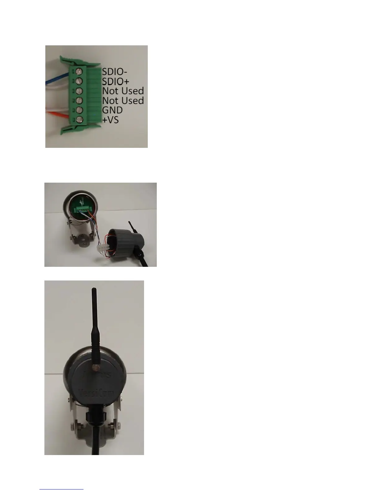
Figure3.1.3(g)
Plug the connector into the socket on the back of the Camera Processor unit, see Figure 3.1.3(h), the
connectoriskeyedandcanonlypluginoneway.
Figure3.1.3(h)
Align the slots in the back cap assembly with the three posts on
theCameraP rocessorunit.Gripthecapassemblyfirmlyandpush
itintoplace.Whenthethree postsarefullyseatedgivethecapa
quarter turn clockwise to fully secure it to the Camera
Processor
unit.Ensurethatthewiresarenot‘pinched’betweenthecapand
the Camera body. Turn the back of the cap assembly so that the
antennaispointedstraightup,seeFigure3.1.3(i).
Theantenna is supplied intheship kit. It is mounted by screwing
totherightanglebracketonthecapassembly.
Pull the camera sun shield back and snug down the camera
bracketsetscrews.Finaladjustmentofthesunshieldwillbedone
laterduringtheFieldOfView(FOV)setupprocedure.
Figure3.1.3(i)


 To Next Page