26
3.3.1 ICC-2W Module Configuration Switches
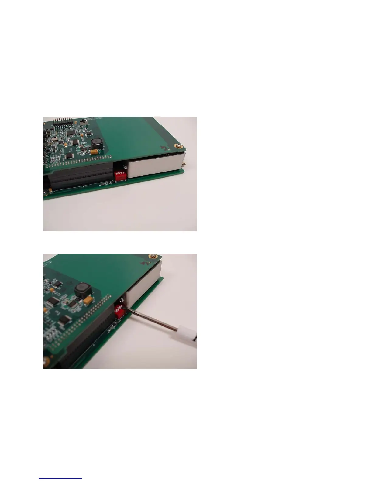
Thereisasetof configurationDIPswitches located on thetopedge of thelowerboard of theICC‐2W
Module,seeFigure3.3.1(a).Theseswitchesareusedtoconfi guretheICCmoduleforuseinaNEMATS‐
2typedetectorrack.Allswitchesshouldbein
the“ON”position(towardsthecardedge)for useinaTS‐
2 type detector rack, see Figure 3.3.1(b). For other rack types the DIP switches should remain in the
“OFF” position (away from the card edge). The position of these switches for operation in racks other
thanaNEMA
TS‐2isnotcritical.
Figure3.3.1(a)
Figure3.3.1(b)



 To Next Page