Micro-JLT GNSS™ User Manual
6 © 2019 Jackson Labs Technologies, Inc.
Connect a terminal program (TeraTerm is recommended) to the unit via an RS-422 or TTL, (the
choice depends on your order option), to a USB serial connector to the appropriate pins on J1 with a
setting of 115.2KB 8N1 and no flow-control. You may also download the GPSCon program
discussed in Chapter 5 from the JLT support website page for free.
WARNING: Do not connect RS-232 serial levels to connector J1. The unit may become
damaged from RS-232 serial levels on connector J1 as the default configuration is
RS-422 differential or TTL levels.
Try some of these typical SCPI commands or refer to Chapter 3 for full list of SCPI commands:
HELP?
SYSTem:STATus?
GPS?
SYNChronization?
MEASure?
DIAGnostic?
*IDN?
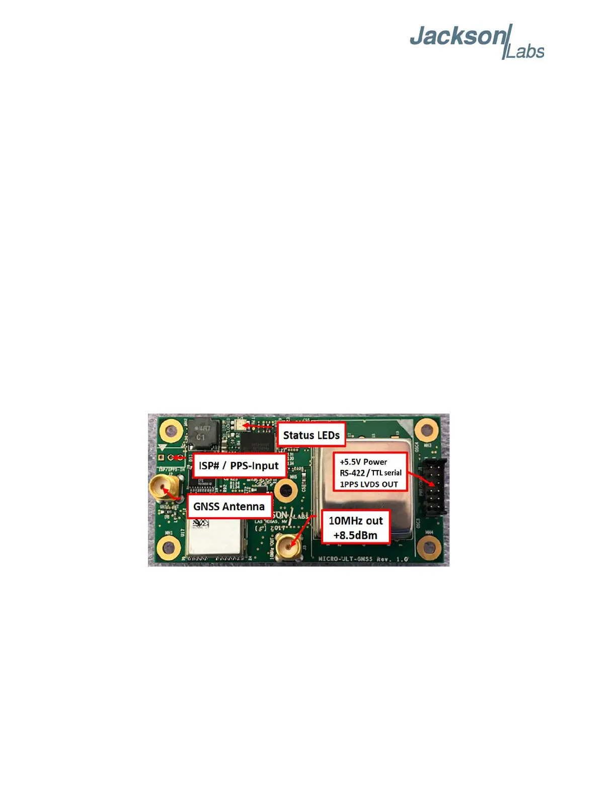
2.1.1 PCB Photos
The Micro-JLT GNSS™ PCB connectors and indicators are shown in Figure 2.1.
Figure 2.1 Micro-JLT GNSS™ Single Oven PCB
A Micro-JLT GNSS™ unit with a double oven OCXO is shown in Figure 2.2.