Micro-JLT GNSS™ User Manual
32 © 2019 Jackson Labs Technologies, Inc.
The Micro-JLT GNSS™ provides a time-stamping ability for an externally-supplied signal with TTL
or CMOS 3.3V/5V input level compatibility. The external signal to be time-stamped will need to be
applied to pin-3 of J4 with pin-2 of J4 being ground, as shown in Figure 3.1 above. Time-stamping
can either be done on the rising or the falling edge of the externally-provided reference signal, as
described in Section 3.6.5 .
A suitable 3-pin, 100-mil pin-spacing connector will need to be soldered onto the board to enable this
optional feature. Please ensure that the externally supplied signal is in the range of -0.5V to 5.0V
maximum at all times including under and overshoot, as lower or higher voltages can damage the
PCB. The time-stamping input pin-3 of connector J4 is pulled low by an internal 5K Ohms resistor.
The rise/fall times of the externally supplied signal to be time-stamped is recommended to be <10ns.
Also refer to Table 2.1 for pin descriptions of connector J4.
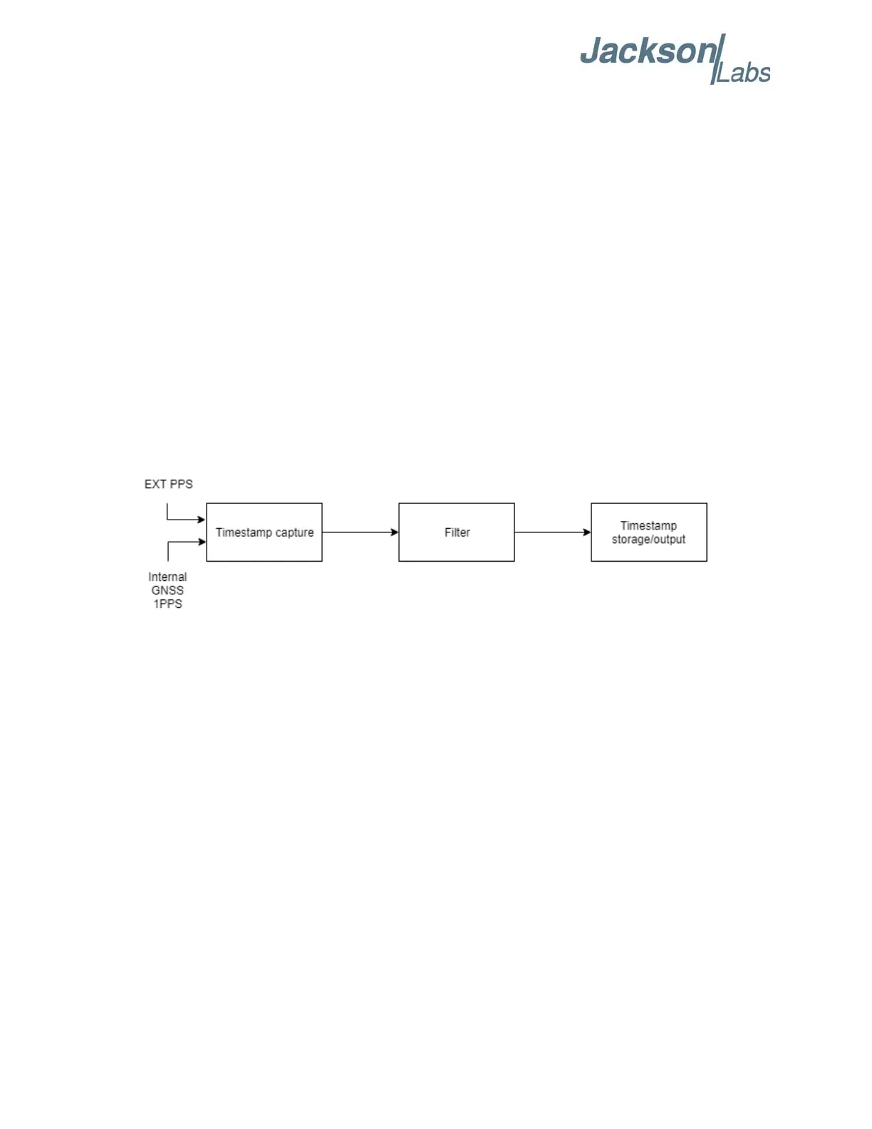
A block diagram is presented in Figure 3.2 to demonstrate the PTIME subsytem time-stamping
capability. The process begins with EXT PPS and internal GNSS 1PPS signals as sources for
time-stamping. These time-stamp sources are captured and alined to UTC time by using the GNSS
1PPS signal as a reference. Next, the time-stamp results may be filtered before output depending on
the user’s preference. Please refer to Section 3.5.15 for more information on filters. Lastly, the
time-stamps can be outputted to the RS-422/TTL serial interface. Please refer to Section 3.5.12 for
more information on time-stamp output.
Figure 3.2 PTIMe:STAMp Block Diagram
3.5.12 PTIMe:STAMp:MODE
<OFF|ASYnc|MEMory|OUTput|DIFFer>
The PTIMe:STAMp:MODE command is unrelated to OCXO disciplining. For more information on
OCXO disciplining, please refer to Section 3.6 .
The board may be configured to record and store time-stamps of a pulse source into memory for later
retieval if any one of ASY, MEM, OUT, or DIFF modes is selected. The unit will store up to 100
time-stamps of the most-recent pulses, including the first and last pulses that arrived within a
one-second interval, and discard all extra time-stamps if there are more than 100 time-stamps.
The unit can process a maximum of 10,000 pulses (10 KHz signal) during the one-second interval.
Connecting a signal with higher frequency such as a 10 MHz reference to PPS input will result in
truncated time-stamp recording. All stored time-stamps are in GPS time-of-week format, with exam-
ple shown below, which contains the week number and week second with nanosecond precision syn-
chronized to the best representation of UTC (USNO) available. Note that the leapsecond offset
provided in PTIMe:LEAPsecond:ACCumulated? response is applied to all stored time-stamps.
By default, PTIMe:STAMp:MODE is in OFF mode which disables the time-stamping of the pulses.
When changed to the ASYnc mode, the Micro-JLT GNSS™ will output the time-stamp of each
accepted pulse instantaneously after the pulse(s) arrive. Configuring the unit to the OUTput mode