5-24 4181384 First Edition
HYDROSTATIC POWER TRAIN
5
Disassembly, Inspection, and Assembly
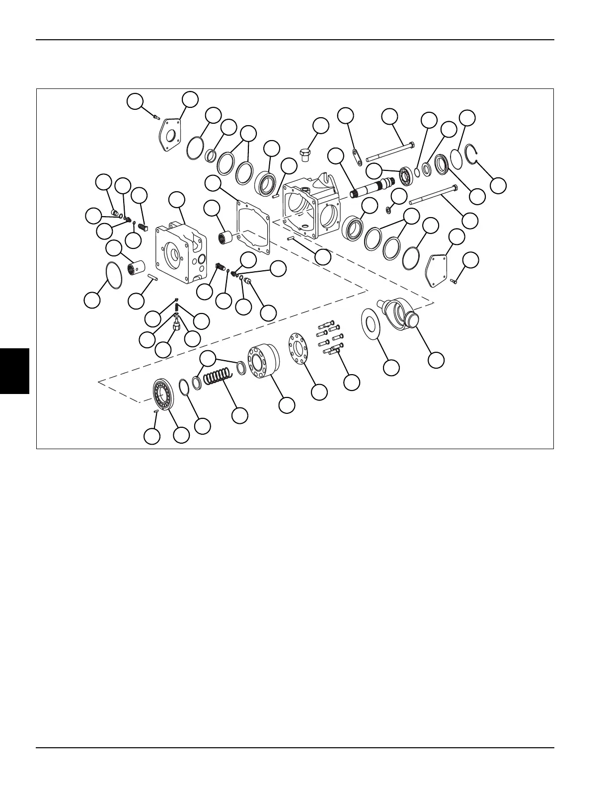
See Figure 5-26.
Figure 5-26
1. Park the mower safely. (See “Park Mower Safely” on
page 1-7.)
2. Remove hydrostatic pump. (See “Traction Pump” on
page 5-22.)
3. Scribe a line along the side of the pump to mark the
position of the pump segments before disassembly.
4. Remove four screws (12) and washers (18) that hold
the pump together.
5. Remove each section of the pump. Look for
identifying marks for assembly.
6. Place parts in assembly order on a clean work area
as they are removed.
1 Screw (8) 13 Retaining Ring 25 Cylinder Block Spring 37 O-Ring (2)
2 Trunnion Cover Assembly 14 Lip Seal 26 Retaining Ring 38 Hex Plug (2)
3 O-Ring (2) 15 O-Ring 27 Valve Plate 39 O-Ring (2)
4 Lip Seal 16 Internal Retaining Ring 28 Pin 40 SCR Valve
5 Shim (3) 17 Seal Carrier 29 Washer (2) 41 Spring Pin
6 Taper Roller Bearing (2) 18 Washer (3) 30 Plug Assembly 42 Pad Seal
7 Pin (2) 19 Trunnion Cover 31O-Ring 43Coupling
8 Hex Plug (3) 20Swash Plate 32Shim Kit 44End Cap
9 Shaft 21 Thrust Plate 33 Spring 45 Needle Bearing
10 Lift Bracket 22 Piston Assembly 34 Charge Relief Poppet 46 End Cap Gasket
11 Ball Bearing 23 Slipper Retainer 35 Special Plug (2)
12 Screw (4) 24 Cylinder Block 36 O-Ring (2)
TN1308
45
23
24
25
22
21
10
12
16
1
4
3
2
5
6
44
5
3
7
8
14
11
17
1
9
46
26
27
28
29
35
34
32
30
13
15
12
19
6
20
33
31
42
41
40
35
38
36
38
40
7
18
43
37
39
37
39
36
 Loading...