CUTTING UNITS
4181384 First Edition 8-45
8
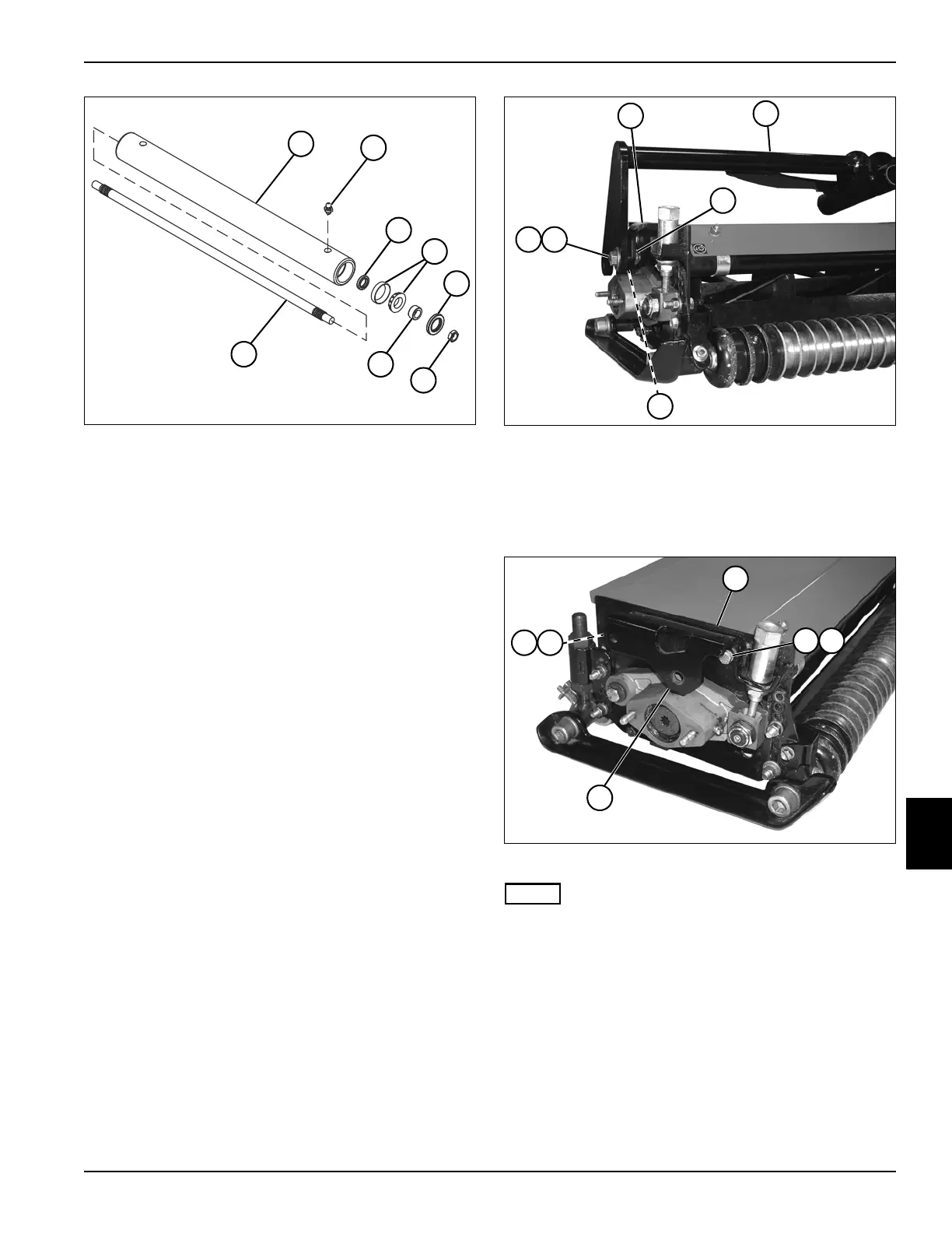
Figure 8-44
4. Remove nut (5) from each end of roller shaft (7).
5. Remove roller shaft (7) from roller (1).
6. Remove components from both ends of roller and
keep in order to ease assembly.
7. Inspect all parts for wear or damage. Replace as
necessary.
Assembly Notes
• Assemble the rear roller by reversing the order of
disassembly.
• After assembly, apply grease to grease fitting (2) on
each end of roller (1). (Refer to “Safety, Operation,
and Maintenance Manual” for grease specifications.)
Yoke Assembly
Removal and Installation
See Figures 8-45 and 8-46.
1. Park the mower safely. (See “Park Mower Safely” on
page 1-7.)
2. Remove the cutting unit. (See “Cutting Unit” on
page 8-36.)
Figure 8-45
3. Remove two (one each side) locknuts (3), screws (5),
flat washer (6), and spacer (4) from yoke assembly
(2) and cutting unit frame (1).
4. Remove yoke assembly (2).
Figure 8-46
NOTE
Perform step 5 if removing the mounting brackets.
5. Remove two screws (8), lock washers (9), and
remove the mounting bracket (10) and spacer (7).
Installation Note
Install the yoke assembly by reversing the order of
removal.
1Roller 5Nut (2)
2 Grease Fitting (2) 6 Wear Sleeve (2)
3 Oil Seal (2) 7 Shaft
4 Bearing, Cup and Cone (2)
TN1271
2
7
5
6
3
1
3
4
TN1265
5 6
2
3
4
1
TN1267
8 9
8 9
7
10