ELECTRICAL
4181384 First Edition 4-81
4
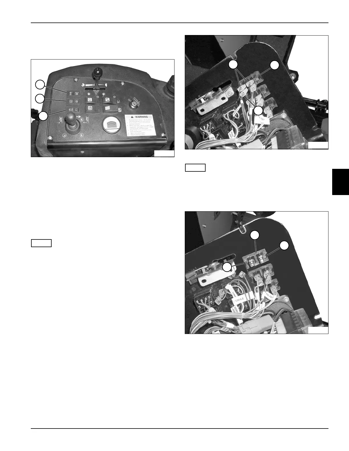
Indicator Lamps
See Figure 4-71.
Figure 4-71
This procedure applies to the following indicator lamps:
• Control Module Warning/Engine Preheat Lamps (1)
• Engine Temperature Warning/Engine Oil Pressure
Warning Lamps (2)
• Block Hydraulic Filter Warning/Charge Warning
Lamps (3)
Removal and Installation
See Figures 4-72 and 4-73.
NOTE
Control module warning/engine preheat lamp module
shown.
1. Park the mower safely. (See “Park Mower Safely” on
page 1-7.)
2. Disconnect the battery negative (–) cables at the
battery.
3. Remove instrument panel. (See “Instrument Panel”
on page 4-76.)
Figure 4-72
NOTE
Label all wiring connectors and record their locations
before removing to ensure correct installation.
4. Disconnect wiring connectors (1) from the indicator
lamp module (2).
Figure 4-73
5. Press in on the tabs (3) on each side of the indicator
lamp module, and push the module (4) through the
panel.
Installation Note
Install indicator lamp module(s) by reversing the order of
removal.
TN1066
2
1
3
TN1091
2
1
1
3
TN1092
4
3