4-84 4181384 First Edition
ELECTRICAL
4
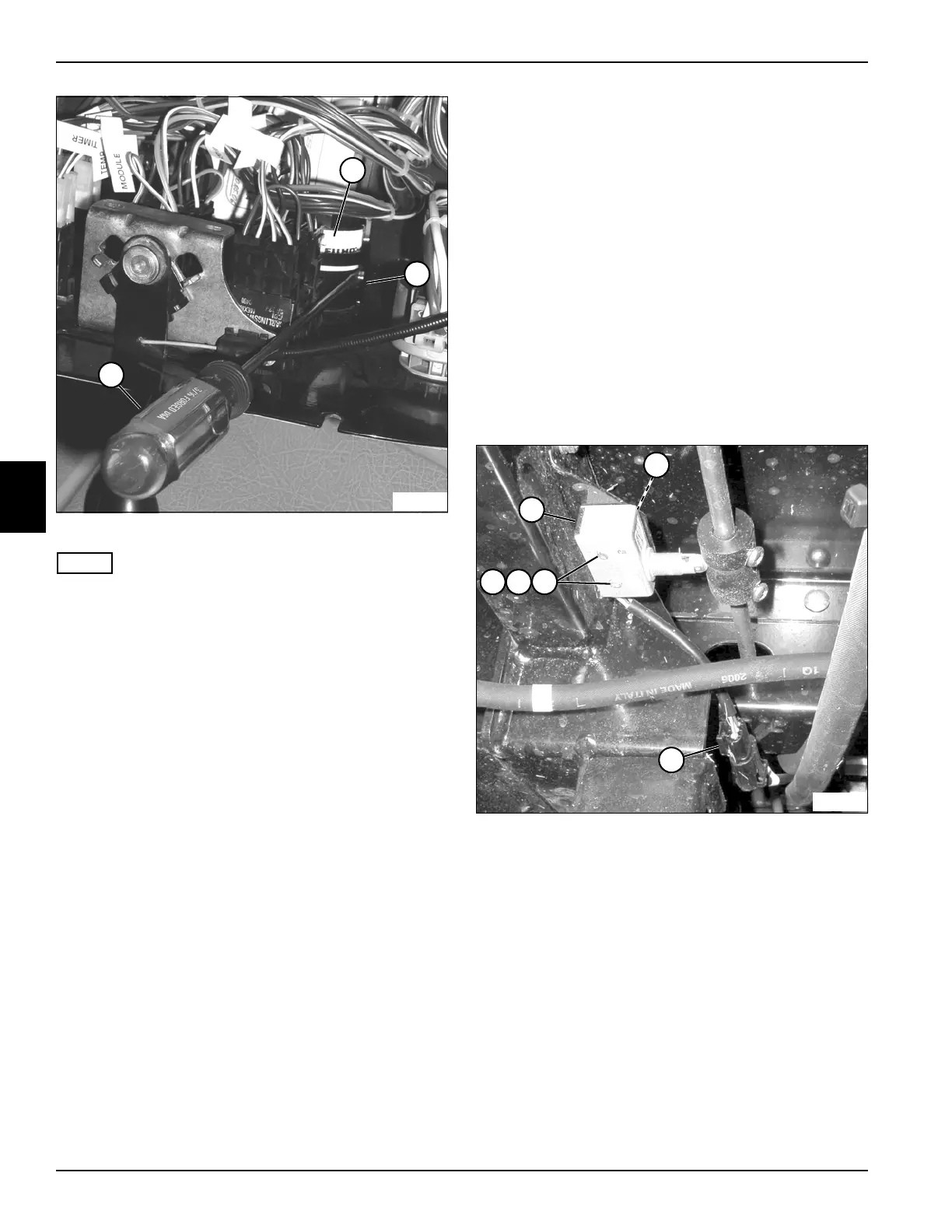
Figure 4-79
NOTE
The bracket must be removed in stages, working from
side-to-side until the bracket is free of the gauge body.
5. Insert a thin flat-bladed screwdriver (5) between the
mounting bracket (4) and gauge body (3), and
carefully pry the bracket away from the gauge body
while lifting the bracket.
Repeat the procedure on the other side of the
gauge/retainer bracket.
Installation Note
Install the multi-function gauge by reversing the order of
removal.
Seat Switch
Removal and Installation
The seat switch removal and installation is included in the
seat and mounting plate removal and installation
procedure. (See “Seat and Mounting Plate” on
page 9-16.)
Traction Pedal Neutral Switch
Removal and Installation
See Figure 4-80.
1. Park the mower safely. (See “Park Mower Safely” on
page 1-7.)
2. Remove the right front mower deck. (See “Rotary
Cutting Unit” on page 8-25.)
Figure 4-80
3. Disconnect the wiring connector (3) from the
harness.
4. Remove two screws (4), lock washers (5), brass
washers (6), and mounting plate (2), and remove
neutral switch (1).
Installation Notes
• Install the neutral switch by reversing the order of
removal.
• Adjust the neutral switch. (See “TR-3 and Early
Model 30001 AR-3 Traction Pedal Neutral Switch
Adjustment” on page 5-20.)
3
TN1231
5
~
4
TN1160
3
6
1
2
5
4