5-32 4181384 First Edition
HYDROSTATIC POWER TRAIN
5
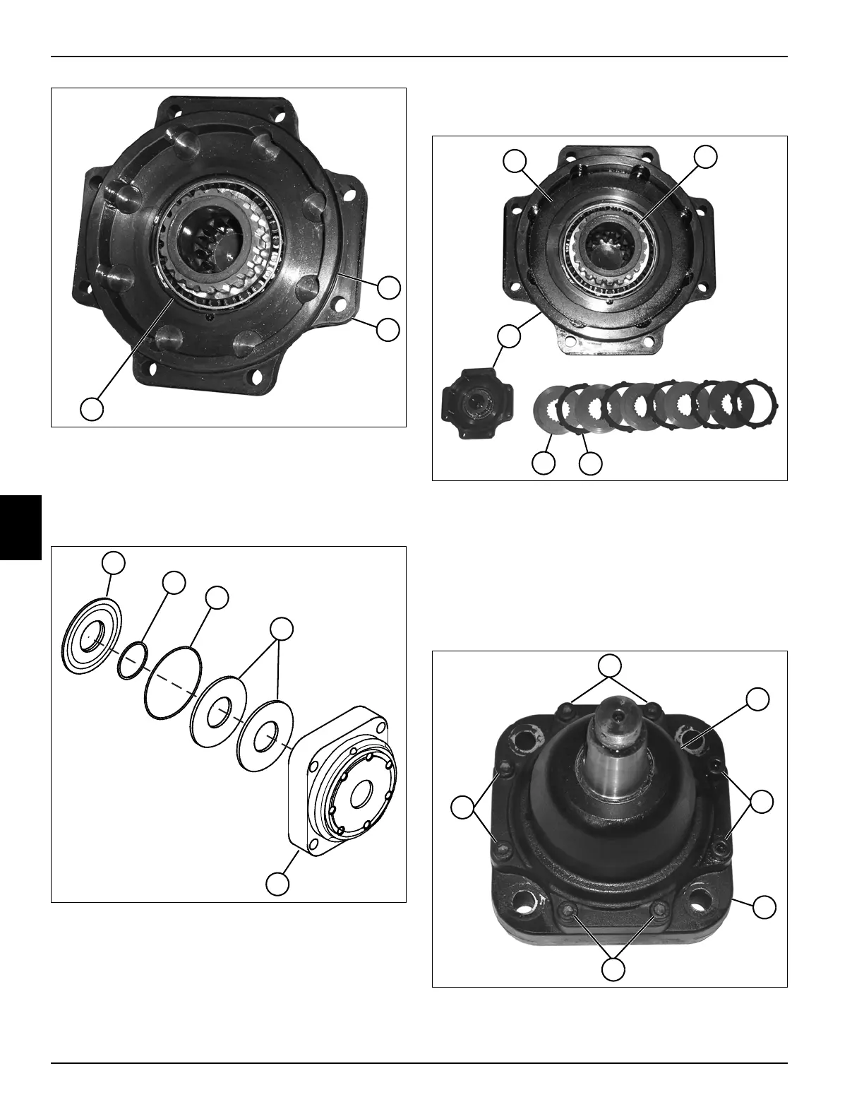
Figure 5-48
5. Install the retaining ring (7) into the groove in the
bearing housing (6).
6. Apply a thin film of petroleum jelly to O-ring (5), and
install O-ring on the bearing housing (6).
Figure 5-49
7. Install the spring discs (11) in the mounting flange
(12) in the same orientation as recorded during
removal.
8. Apply a thin film of petroleum jelly to O-rings
(9 and 10), and install O-rings on the brake piston
(8).
9. Install the brake piston (8) in the mounting flange (12)
in the same orientation as recorded during removal.
Figure 5-50
10. Install the brake disks (16) and stator rings (13) in the
bearing housing (15) and output shaft (14).
Install a stator ring (13) first, aligning the tabs with
the detents in the bearing housing (15), followed by a
brake disk (16), installed over the output shaft
splines. Continue installation by alternating a stator
ring and brake disk.
Figure 5-51
TN1317
5
7
6
TN1339
12
11
8
9
10
TN1322
13
14
~
13
15
16
TN1315
17
17
17
17
18
19