Page 18
3.5 Temperature Sensors
1. Drill 3/8" hole in pipe between filter
pump and filter and install the Water
Temperature Sensor per instructions
(make certain the o-ring is in place).
2. Install
Air Temperature Sensor outside the
Power Center can, not in direct sunlight and
away from motors and other heat sources.
3. Install Solar Temperature Sensor
(optional) adjacent to solar panels.
NOTE If a solar sensor (or a 2.2K Ohms resistor) is not
installed, the solar button can be labeled and
used as an extra auxiliary.
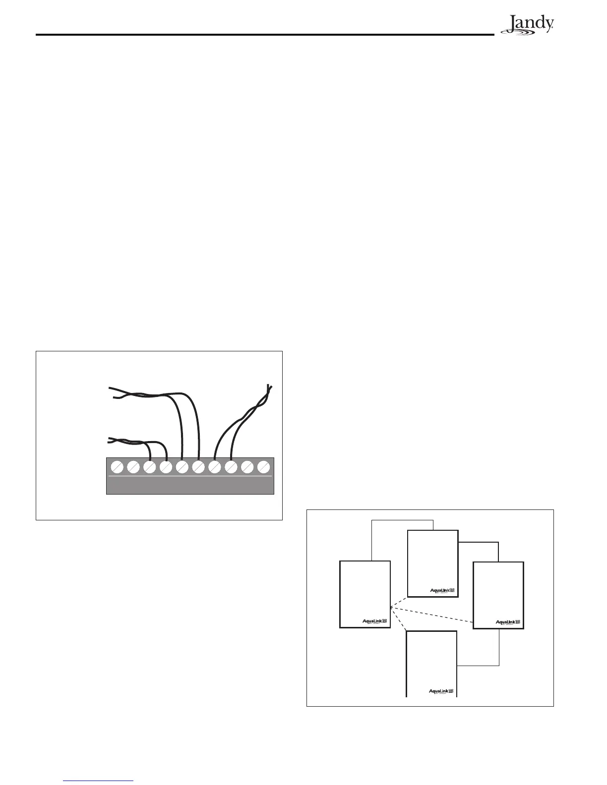
4. Run the wire to the Power Center, through
the low voltage raceway. Cut off excess
wire. Strip the wire jacket back 6", then
strip each wire ¼". Connect sensor wires to
the green, 10-pin terminal bar (see Figure
17).
3.6 JandyValveActuators
NOTE Mount the JVA's according to the Jandy Valve
Actuator Installation and Operation Manual.
JVA cable is type SJW-A marked water resistant
class 3 cable and does not require conduit.
Knockouts and Heyco fittings are provided in the
Low Voltage Raceway.
1. Route the JVA wire to the Power Center.
Figure 17. Temperature Sensor Wiring for a Pool/Spa
Combination
Water
Temperature
Sensor
Freeze/Air
Temperature
Sensor
Solar
Temperature
Sensor
Green 10-Pin Terminal Bar
2. Run the wire through the low voltage
raceway and plug the JVA connectors into
their proper sockets (see Section 6. Power
Center Wiring Diagram). Verify that the
JVA on the suction plumbing is connected
to the Intake JVA Socket, and the discharge
plumbing is connected to the Return JVA
Socket.
NOTE Do not coil the JVA wires inside Power Center.
To shorten the wire, remove the JVA cover
and disconnect the wire. Shorten, strip, and
reconnect.
3. For alternate plumbing configurations the
JVA cam settings can be adjusted as needed.
See the Jandy Valve Actuator Installation
and Operation Manual, Cam Setting Chart
for proper settings.
3.7 Auxiliary Power Centers
AquaLink RS All Button models support one (1)
Auxiliary Power Center.
AquaLink RS OneTouch models support a
maximum of three (3) Auxiliary Power Centers.
1. The auxiliary power centers may be wired
"in series", starting from the Primary Power
Center (solid line) or wired "in parallel"
from the Primary Power Center (dashed
line). See Figure 18.
Primary
Power
Center
or
PureLink
Figure 18. Wiring Multiple Power Centers

 Loading...