Page 19
2. Run four conductor, 22 AWG or larger
cable between the red, 4-pin terminal bars
in each Power Center.
NOTE
• All temperature sensors, heater connections
and the main filter pump must be wired to the
Primary Power Center.
• Never put more than two (2) wires into each
of the pins of the red, 4-pin terminal bar (use
a Jandy Multiplex Board).
• If more than one Auxiliary Power Center is
installed, set the jumpers as shown in Figure
19.
Figure 19. Setting Jumpers for Multiple Auxiliary
Power Centers
Aux. PC #1
(AUX B1 to B8
for RS12, 16,
2/10, 2/14)
W1
W2
Aux. PC #2
(AUX C1 to
C8 for RS24,
2/22)
Aux. PC #3
(AUX D1 to D8 for
RS32, 2/30)
W1
W2
W1
W2
(No Jumpers on the Primary Power Center PCB)
3.8 All Button Control Panel Installation
3.8.1 SingleIndoorControlPanel
1. With the aid of the homeowner, find the
best location for the Control Panel.
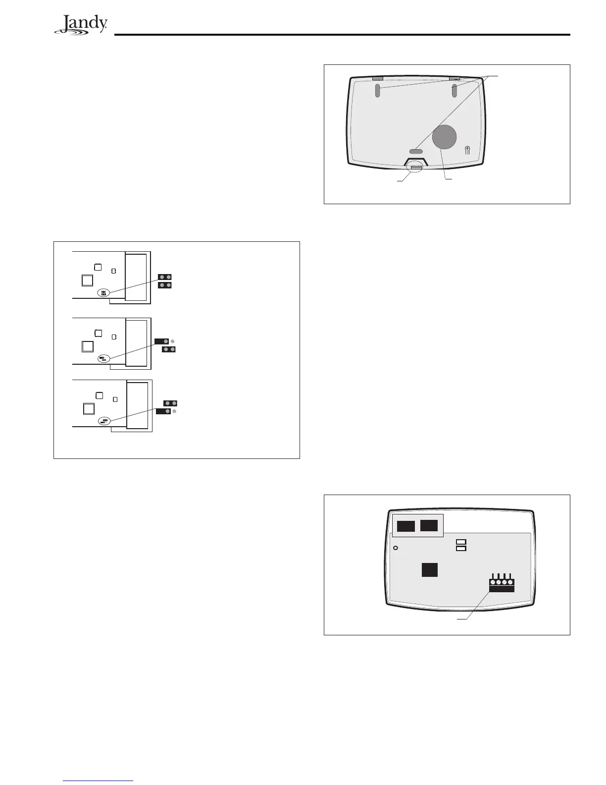
2. Open the Indoor Control Panel Assembly by
pressing in on the tab located on the lower
end of the back of the control panel (see
Figure 20). Place the back of the control
panel against the wall. Level the back of
the control panel and mark the three (3)
mounting screw holes and the cable access
hole.
3. Drill ¼" holes at the three (3) mounting
screw marks and insert the plastic anchors.
Drill a 1¼" (min.) to 2" (max.) hole for
cable access.
4. Mount the back of the control panel housing
to the wall and secure in place.
5. Pull the 4-conductor, 22 AWG or larger
cable through the access hole and tie a loose
knot to prevent the cable from slipping back
through the access hole. Strip cable jacket
6", and each individual wire ¼".
6. Remove the red, 4-pin terminal bar from the
control panel PCB. Connect the 4 conductor
cable to the red, 4-pin terminal bar (see
Figure 21). Reconnect the red, 4-pin
terminal bar back to the Control Panel PCB.
Mounting
Screw Holes
4-Conductor Cable
Access Hole
Tab
Figure 20. All Button Control Panel - Back View
Figure 21. All Button Control Panel PCB
Red 4-Pin Connector
Green
Yellow
Black
Red
7. Hang the Control Panel front over the two
tabs at the top of the control panel back.
Swing the bottom of the Control Panel front
down and snap into place.

 Loading...