Page 21
Green
Yellow
Black
Red
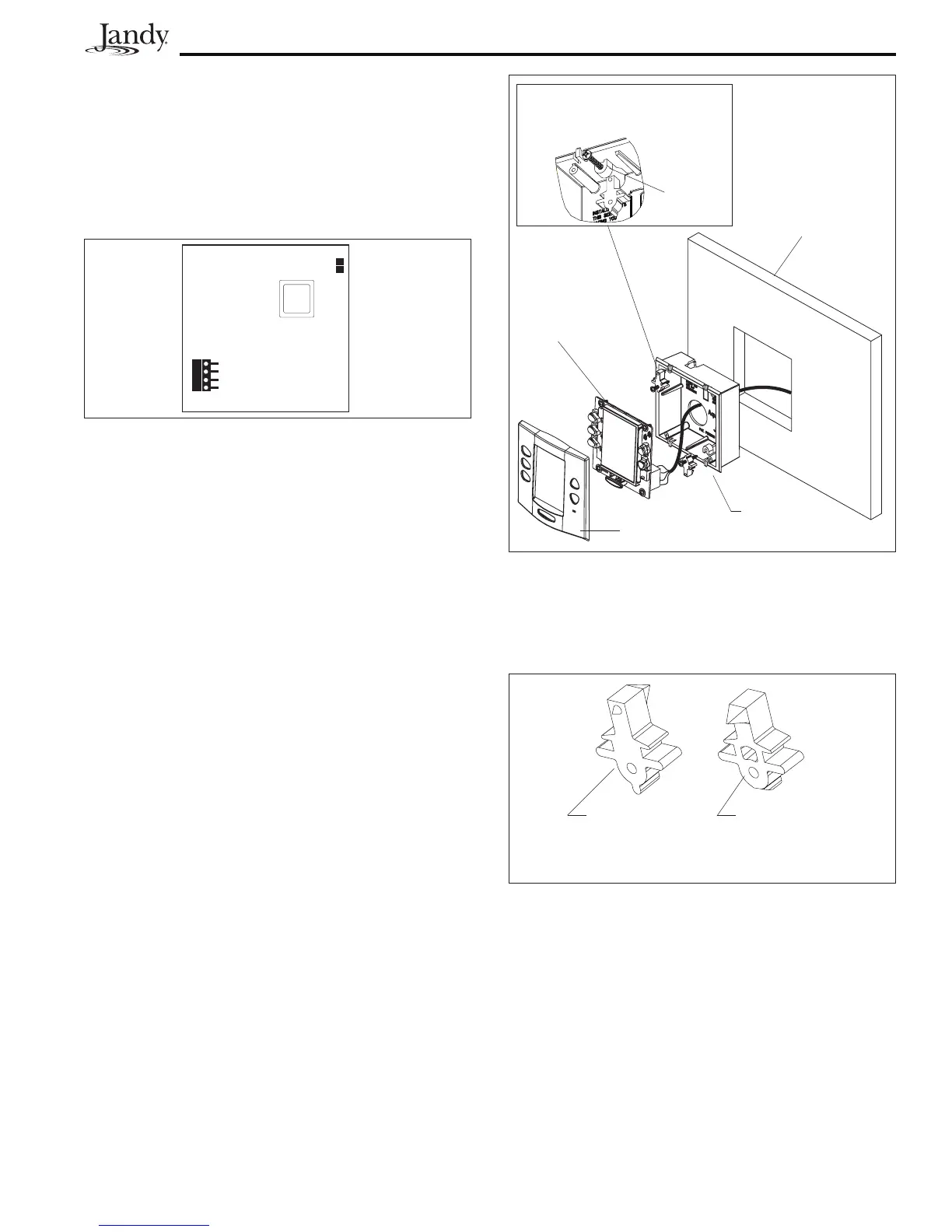
Figure 25. OneTouch PCB - Back View
3.9.2 FlushMountOneTouchInstallation
1. With the aid of the homeowner, find the
best location for the Control Panel.
2. Place the Flush Mount box in the location
chosen for the Control Panel. Level the box
and trace around the outside of the box with
a pencil. Cut the hole being careful not to
oversize.
3. Route the 4-conductor cable from the Power
Center to the Indoor Control Panel.
4. Pull the 4-conductor cable through the hole
in the wall and the hole in the flush mount
box. Push the flush mount box into the hole
in the wall with the correct orientation (see
Figure 26).
5. Depending on what size sheet rock (5/8" or
1/2"), determine which side of the cleat is to
be facing you (see Figure 27).
Figure 27. Cleat Orientation
This side
faces towards
you for 5/8"
sheetrock.
This side
faces towards
you for 1/2"
sheetrock.
6. Insert a screw through the screw boss (see
Figure 26). Put a cleat into the top "U"
shaped hole. Hand tighten the screw and
repeat the process for the bottom cleat.
7. Wire the 4-conductor cable to the red, 4-pin
terminal bar. Push the 4-pin terminal bar
onto the back of the OneTouch PCB. Place
the OneTouch PCB back into the Flush
Mount Housing. Insert the screws with
rubber washers and hand tighten. Do not
overtighten. Snap the faceplate into place.
5. Wire the 4-conductor cable to the red, 4-pin
terminal bar (see Figure 25). Push the 4-pin
terminal bar onto the back of the OneTouch
PCB. Place the PCB with LCD and buttons
back into the box. Insert the screws and
hand tighten. Do not overtighten. Snap the
Faceplate into place.
Sheet Rock
(1/2" or
5/8" with a
4" square
cutout)
Flush Mount
Housing
Faceplate
OneTouch PCB
Slide cleat into the slot opening,
thread screw through the boss
and into cleat.
Boss
Figure 26. OneTouch Flush Mount Installation

 Loading...