Page 23
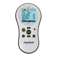
4. Feed the four conductor wire into the Power
Center through the low voltage raceway.
5. Cut off the excess wire. Strip the jacket
back 6" and strip the individual wires
approximately ¼". Connect the four
conductor wire to the red terminal bar on
the Power Center PCB.
6. Install the dead panel to the Power Center
and restore all power.
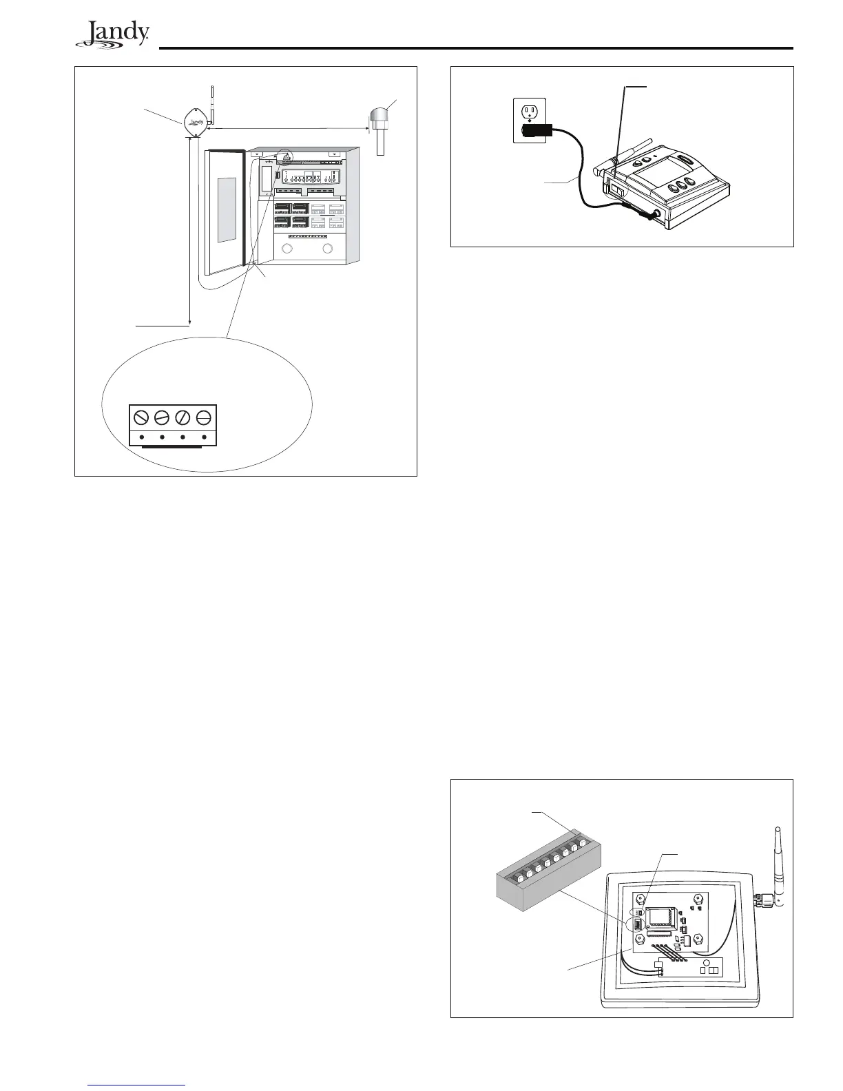
3.10.2 IndoorControlPanelInstallation
1. Connect the transformer to the back of the
control panel (see Figure 31).
2. Plug the transformer into a wall socket.
3. Charge for 24 hours before removing
the Power Supply/Charger (the system is
operational while charging).
J-box
Transceiver
6'
Low Voltage Raceway
Minimum 8'
Air
Blower
Power
Center
Ground
Level
3 Yellow
1 Red
2 Black
4 Green
Red 4-Pin
Terminal Bar
Figure 30. Outdoor Transceiver J-box Installation
for Wireless OneTouch Control Panel
When not in use, turn
the ON/OFF Switch to
the off position.
Power Supply/
Charger Cord
Figure 31. Wireless OneTouch Control Panel
Installation
3.10.3 ChangingtheTransmissionCode
If your AquaLink RS system is turning items on
or off at undesignated times, another AquaLink
RS Wireless Control Panel may be in close
proximity using the same or similar code. To
prevent unwanted operation, the code for your
AquaLink RS Wireless system can be personalized.
Except for DIP switch #8, both the Power Center
Transceiver and the Control Panel Transceiver
must be set to the same code. The Indoor Control
Panel Transceiver DIP switch #8 must be OFF and
the Power Center Transceiver DIP switch #8 must
be ON.
1. At the Indoor Control Panel, remove the
screws to expose the transceiver PCB.
2. Locate the small set of DIP switches on the
Control Panel PCB (see Figure 32). Except
for DIP switch #8, turn on one or more
DIP switches. Important- Before installing
the Control Panel cover, press the reset
button (SW1). Note which switches you
have turned on then reinstall the cover and
screws.
Always OFF
If any DIP Switch is moved, you
must press SW1 to establish
communication (may need to press
more than one time).
SW1
Indoor Control
Panel Transceiver
PCB
Figure 32. DIP Switch Settings at Wireless Indoor
Control Panel

 Loading...