VS-FHP2.0 20A 12
*Assumesthree(3)copperconductorsinaburiedconduitand3%maximumvoltagelossinbranchcircuit.AllNationalElectricalCode
(NEC)ortheCanadianElectricalCode(CSA)andlocalcodesmustbefollowed.Tableshowsminimumwiresizeandbranchfuse
recommendationsfortypicalinstallation.
The VS-FHP pump can be operated by one (1)
of three (3) controllers: the variable-speed controller,
the AquaLink
®
RS controller (Rev O or later), or the
AquaLink PDA (Rev 4.0 or later). The FloPro variable-
speed pump communicates with the controllers via a
four-wire RS-485 interface.
The VS-FHP pump comes equipped with a factory
installed four-wire RS-485 cable. This RS-485 cable
comes with an additional shielded wire for grounding.
The shielded wire is to be grounded ONLY at
one end, at the VS-FHP pump. This is pre-installed at
the factory. At the other end, the shielded wire is pre-
trimmed at the factory.
If you need to cut the RS-485 cable to any custom
length, make sure to peel back and trim the ground
shielded wire.
To install the variable-speed controller:
TheinstallermustTURNONswitches1and2atthe
VS-FHPpumpwhenconnectedtothevariable-speed
controller.
Thevariable-speedcontrollerpartno.isJEP-R.
1. Remove power from the VS-FHP pump by
disconnecting the high voltage lines or by opening
any breaker to which the VS-FHP pump power is
connected.
Turnoffallswitchesandthemainbreakerinthe
VS-FHPpumpelectricalcircuitbeforestartingthe
procedure.Failuretocomplymaycauseashock
hazard,resultinginseverepersonalinjuryordeath.
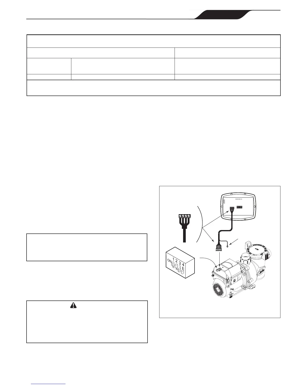
2. Slide dip switches 1 and 2 up, so they are in the
ON position, and slide switches 3 and 4 down, so
they are in the OFF position. See Figure 4.
4-Position
DIP Switch
Variable-Speed
Pump
NOTE
Grounding Lug
RS485
Cable
BLACK
YELLOW
RED
GREEN
RS485
4 3 2 1
RED
BLACK
YELLOW
GREEN
REMOTE CONTROL
5 4 3 2 1
INPUT 2
INPUT 3
INPUT 4
COMMON
INPUT 1
Controller
(Rear View)
The VS-FHP pump comes with a
factory installed four-wire RS-485 cable.
3. Connect the other end of the cable to the
controller. Match the colors of the wires with the
appropriate connector positions as follows: 1- red,
2- black, 3- yellow, and 4- green.
4. Restore power to the VS-FHP pump and verify the
operation of the controller.
5. Refer to the Variable-Speed Controller Owner’s
Manual, H0311200, to operate the pump.
Page 11
Jandy
®
FloPro™ Variable-Speed Pump Series VS-FHP
|
Installation and Operation Manual
ENGLISH