1. Make sure that the pump is turned off.
2. Make sure that the switch to the circuit breaker
that powers the pump motor is turned off.
Turnoffthepumpandthemainbreakerinthepump
electricalcircuitbeforestartingtheprocedure.Failure
tocomplymaycauseashockhazard,resultingin
severepersonalinjuryordeath.
Duetothepotentialriskoffire,electricshock,or
injuriestopersons,Zodiac
®
Pumpsmustbeinstalled
inaccordancewiththeNationalElectricalCode
(NEC),alllocalelectricalandsafetycodes,and
theoccupationalSafetyandHealthAct(OSHA).
CopiesoftheNECmaybeorderedfromtheNational
ProtectionAssociation,470AtlanticAve.,Boston,
MA02210,orfromyourlocalgovernmentinspection
agency.
InCanada,ZodiacPumpsmustbeinstalledin
accordancewiththeCanadianElectricalCode
(CEC).
To install an AquaLink
®
RS controller (Rev O or
later) or an AquaLink PDA (Rev 4.0 or later):
1. Remove power from the VS-FHP pump by
disconnecting the high voltage lines or by opening
any breaker to which the VS-FHP pump power is
connected.
Turnoffallswitchesandthemainbreakerinthe
VS-FHPpumpelectricalcircuitbeforestartingthe
procedure.Failuretocomplymaycauseashock
hazard,resultinginseverepersonalinjuryordeath.
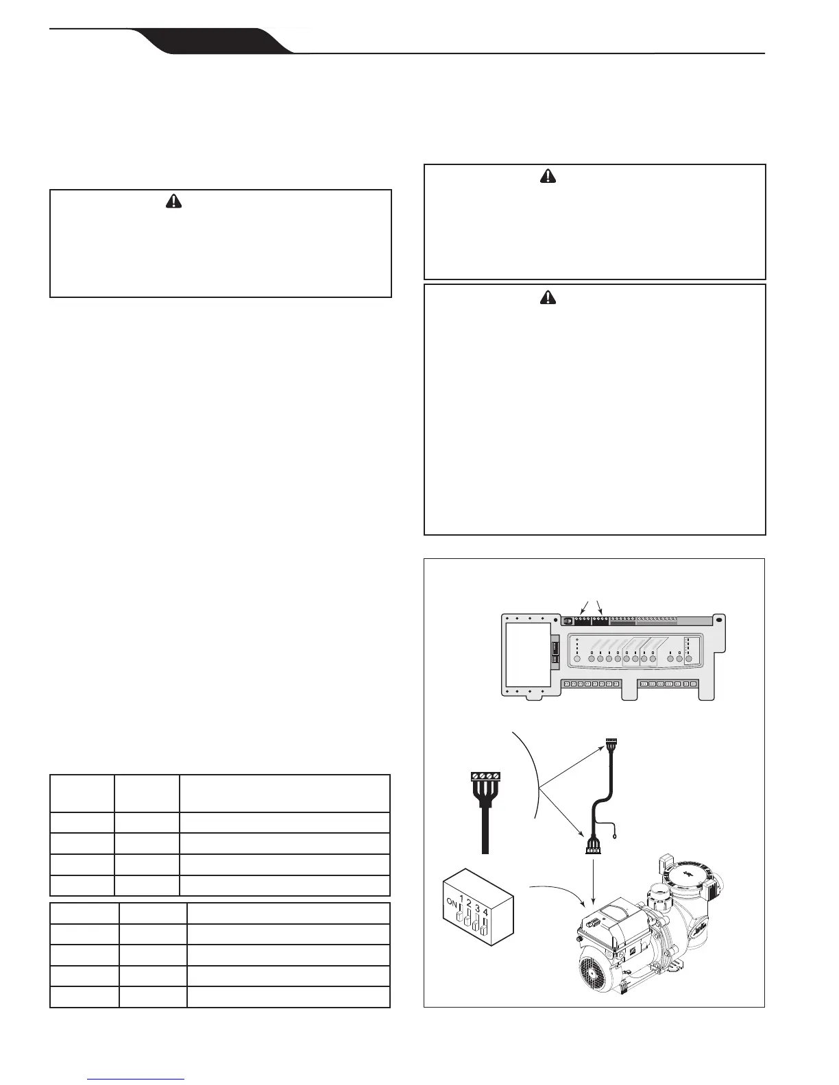
2. Slide dip switches 1 and 2 down, so they are in the
OFF position. See Figure 5.
3. Select the desired address(es) for the VS-FHP
pump by setting dip switches 3 and/or 4, as shown
in Section 3.3, VS-FHP Pump Dip Switch Settings.
4. Connect the other end of the cable to an RS-485
connector on the AquaLink RS (or multiplexer
interface board), matching wire colors with
connector positions as follows: 1-red, 2-black,
3-yellow, and 4-green. See Figure 5.
5. Restore power to the VS-FHP pump and verify the
operation of the controller.
6. Refer to the appropriate manual to operate the
pump: AquaLink RS Owner’s Manual, 6593, or
AquaLink PDA Owner’s Manual, H0572300.
As shown in Figures 4 and 5, the 4-position dip
switch is located at the rear of the VS-FHP pump. This
dip switch serves two (2) functions: it selects the pump
address, and it determines what type of controller will
be used with the pump. The tables below show the dip
switch settings.
OFF OFF AquaLinkRSorAquaLinkPDA
ON OFF AquaLinkRSorAquaLinkPDA
OFF ON AquaLinkRSorAquaLinkPDA
ON ON VariableSpeed
ControllerJEP-R
OFF OFF PUMP1
ON OFF PUMP2
OFF ON PUMP3
ON ON PUMP4
Variable-Speed
Pump
4 3 2 1
RED
BLACK
YELLOW
GREEN
RS485
Cable
BLACK
YELLOW
RED
GREEN
Connect to
AquaLink RS
RS-485 Connector
(or Multiplexer
Interface Board)
S1
S2
RESET
SERVICE
TIME OUT
FILTER PUMP
AUX 1
AUX 2
AUX 3
AUX 4
AUX 5
AUX 6
AUX 7
RS6 & RS8 ONLY
RS8 ONLY
HEATER
SOLAR
POOL MODE
SPA MODE
SPA DRAIN
SPA FILL
AUTO
6 5 4 3 2 1
10 9 8 7 6 5 4 3 2 1
4 3 2 1
4 3 2 1
AquaLink RS
RS-485 Connectors
4-Position
DIP Switch
Page 12
Jandy
®
FloPro™ Variable-Speed Pump Series VS-FHP
|
Installation and Operation Manual
ENGLISH