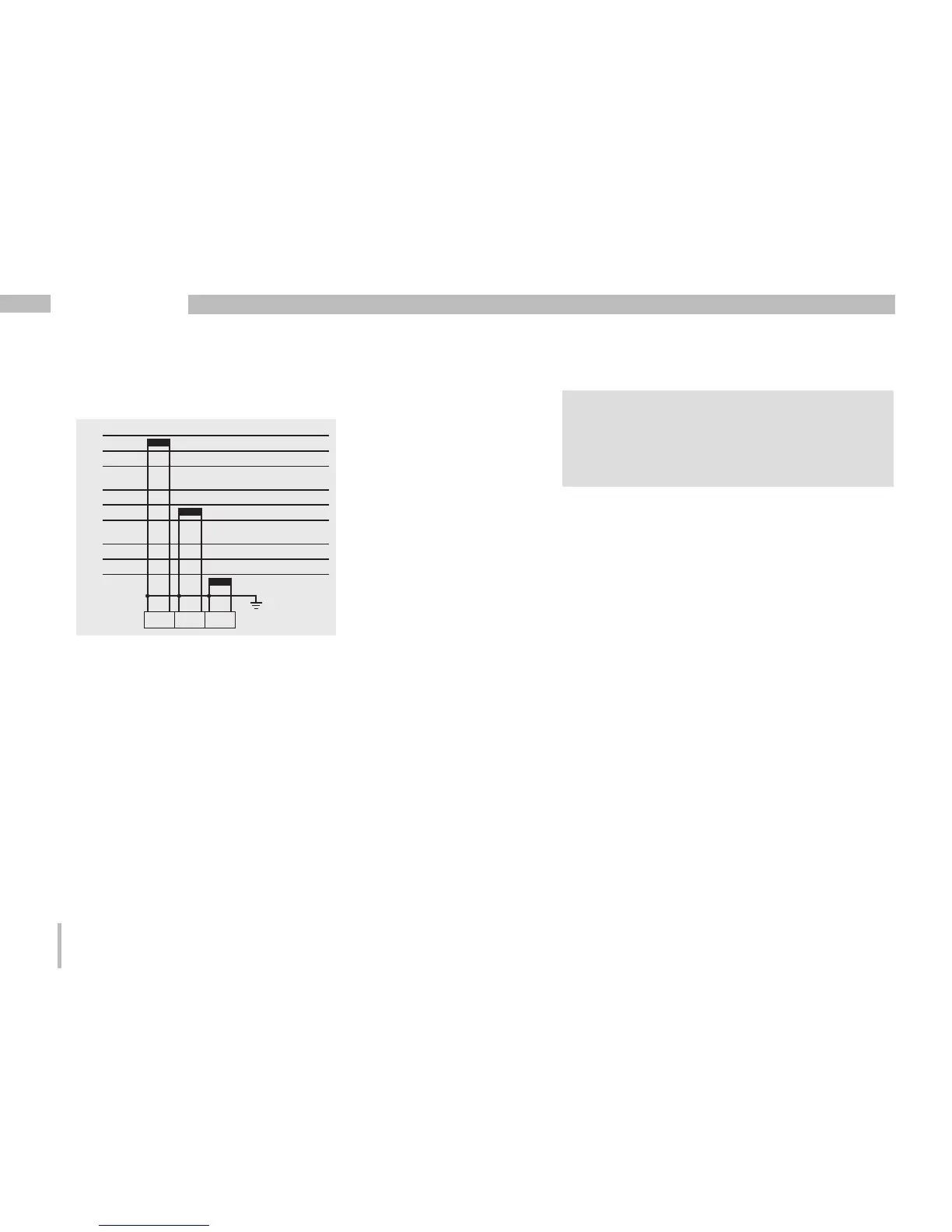
Connection diagram, current measurement
L1
L2
L3
I1 I2 I3
L1
L2
L3
L1
L2
L3
• 3p 1w (addr. 510 = 8)
Fig. Three systems with uniform phase load-
ing. The current measurement values of the
phases of the respective system where are no
CTs connected are calculated (I2/I3 resp. I1/I3
resp. I1/I2).
c
Caution!
The UMG96RM-M is only approved for
a current measurement using the current
transformer.

 Loading...