29
UMG 96RM-M
M-Bus interface
The M-Bus interface is designed with the UMG 96RM-M
as a 2-pole plug contact and communicates via the M-
Bus protocol.
The UMG 96RM-M loads the M-Bus with an M-Bus de-
vice load of 1.5 mA.
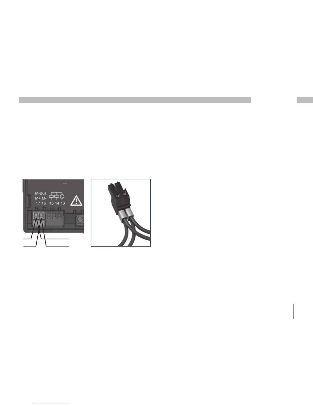
M-Bus interface,
2-pole plug contact
M+
M-
Cable connections
Twisted screened cable should be used for connections
via the M-Bus interface.
• Cable paths should be designed to be as short as
possible.
• Maintain as much distance as possible to power ca-
bles and to consumers (e.g. electrical motors, neon
tubes, transformers).
• In order to prevent cross currents in the bus, there
should be no ground coupling, or a maximum of one
instance of ground coupling.
• Gather the cables mechanically above the earthing
clamp in order to avoid damage due to cable move-
ments.
• Use suitable cable glands to feed the cables into the
cabinet - for example armoured conduit couplings.
2-pin connector with cable
connection ( cable type: 2 x
0.75 mm
2
) via twin ferrules

 Loading...