24
UMG 96RM
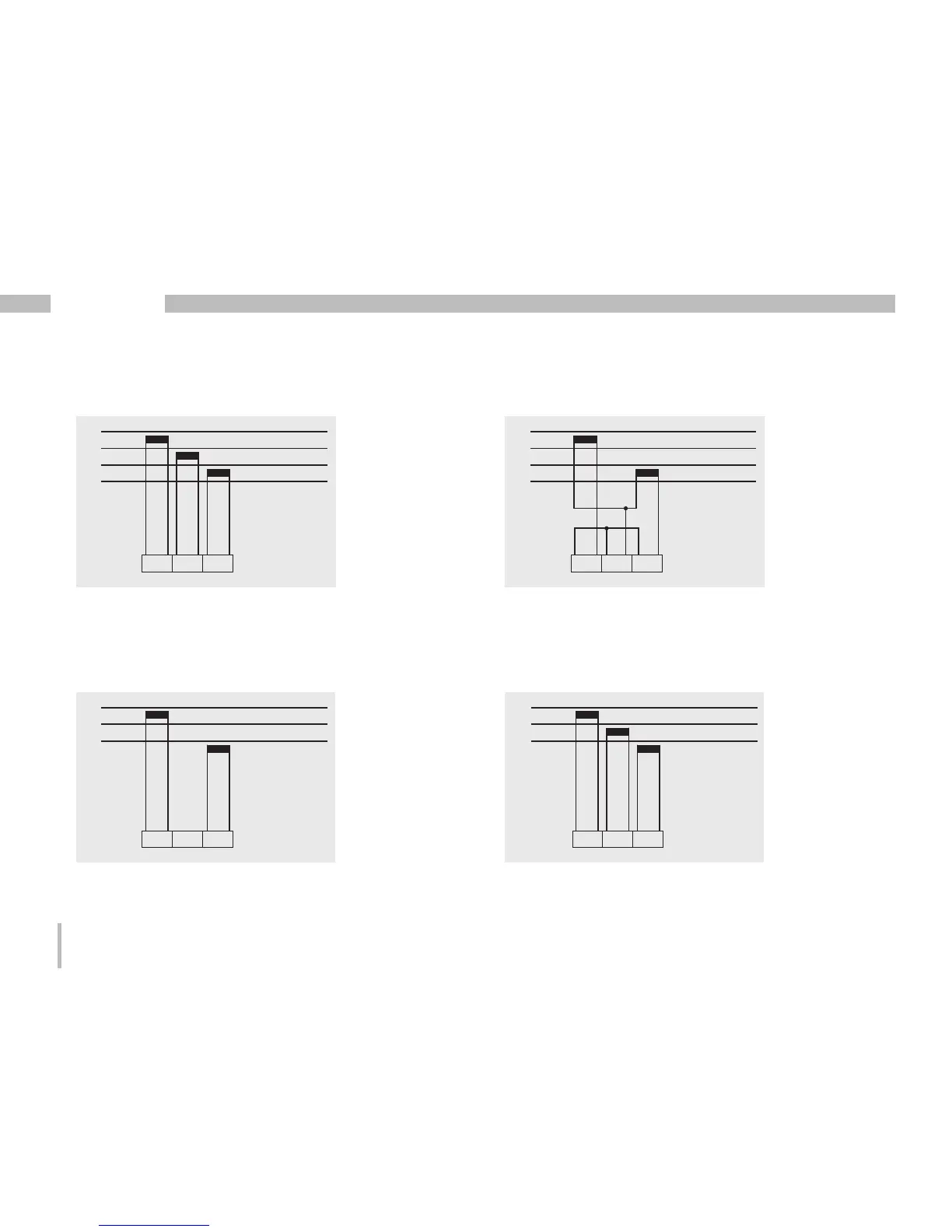
Connection diagram, current measurement
L1
L2
L3
N
I1 I2 I3
• 3p 4w (addr. 510= 0), factory setting • 3p 2i (addr. 510 = 1)
L1
L2
L3
N
I1 I2 I3
L1
L2
L3
I1 I2 I3
• 3p 2i0 (addr. 510 = 2)
L1
L2
L3
I1 I2 I3
• 3p 3w3 (addr. 510 = 3)
Fig. Measurement in a three-phase net-work
with an unbalanced load.
Fig. The measured values for the I2 current
measurementinput are calculated.
Fig. System with uniform phase loading. The
measured values for the I2 current measurement
input are measured.
Fig. Measurement in a three-phase net-work
with an unbalanced load.

 Loading...