Page 34
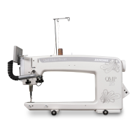
Quit Maker Pro 18 VERSA
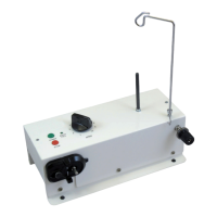
When you rst power on the Quilt Maker Pro 18
VERSA, each of the LEDs in the control board LED
bank will briey ash in succession. Following that
inial ash, the LED (labeled HrtBt) should ash in a
“heart beat” fashion to indicate that the processor is
running and is not locked up. If the processor is locked
up, this LED will be locked in either an “On” or an
“O” state.
A descripon of each of the 8 LEDs and its funcon is
listed below:
• D3 “HrtBt”: Flashing in a “heartbeat” fashion
indicates the processor is running.
• D6 “Speed”: Flashes 100 mes per revoluon of the
hand wheel.
• D5 “Opon”: Should be on when the stch
regulaon overspeed alarm is on.
• D4 “Needle”: Should be O when the take-up lever
is all the way in the Up posion. Should be On when
the take-up lever is down or anyme it is not fully in
the Up posion.
• D10 “Test 4”: Should ash rapidly when
communicaon with the handlebars is established.
• D9 “Test 3”: Transmit LED should ash rapidly when
communicaon with the handlebars is established.
• D8 “Test 2”: Should be On when stch Regulaon is
on.
• D7 “Test 1”: Turns on when the “Start” buon
is pressed, indicang that the motor should be
running. (Go LED)
Near the top of the control board are two green LEDs.
The control board receives an input of +48V from
the power supply and it converts this voltage into
two dierent voltage levels. The le LED (closest to
the +18Vdc label) indicates that the 18V power is
funconing and the right LED (closest to the +5Vdc
label) indicates that the 5V power is funconing.
If either of these LEDs is not on, rst disconnect all
cables from the control board except the red/black
power connector at the top. If the LED(s) are sll
not on, then there may be an issue with the on-
board power supply. If the LEDs both begin working
again, this may indicate that one of the peripherals is
shorng out the control board.
Begin plugging the cables back in one at a me
(powering o between the connecon of each cable)
unl you nd the cable that is causing the issue. If
it is a handlebar cable, then the issue could be the
internal cable, the external cable, or the handlebar
itself. You could then try plugging that cable back in
with the handlebar disconnected to verify whether
it is the cable or the handlebar. If it is one of the
other cables, then the problem may be related to
that parcular component (needle/speed encoder or
motor driver).
However, if both LEDs are o, check to make sure the
black power cord is plugged in and the power switch
is ON. A volt meter may be used to verify that there
is 48V DC between the red/black connector on the
top of the control board. If you do not have 48V DC,
then the power supply and aached cables should be
inspected for any short circuits or wires breaking away
from connectors, both on the control board side and
power supply side. If the volt meter indicates that the
48V is present at the control board power connector
and the control board power LEDs are o, then the
C-Pod should be replaced.
LED Idencaon Control Pod Power LEDs
 Loading...