2. CONNECTION TO TRACTOR
PR11-0356
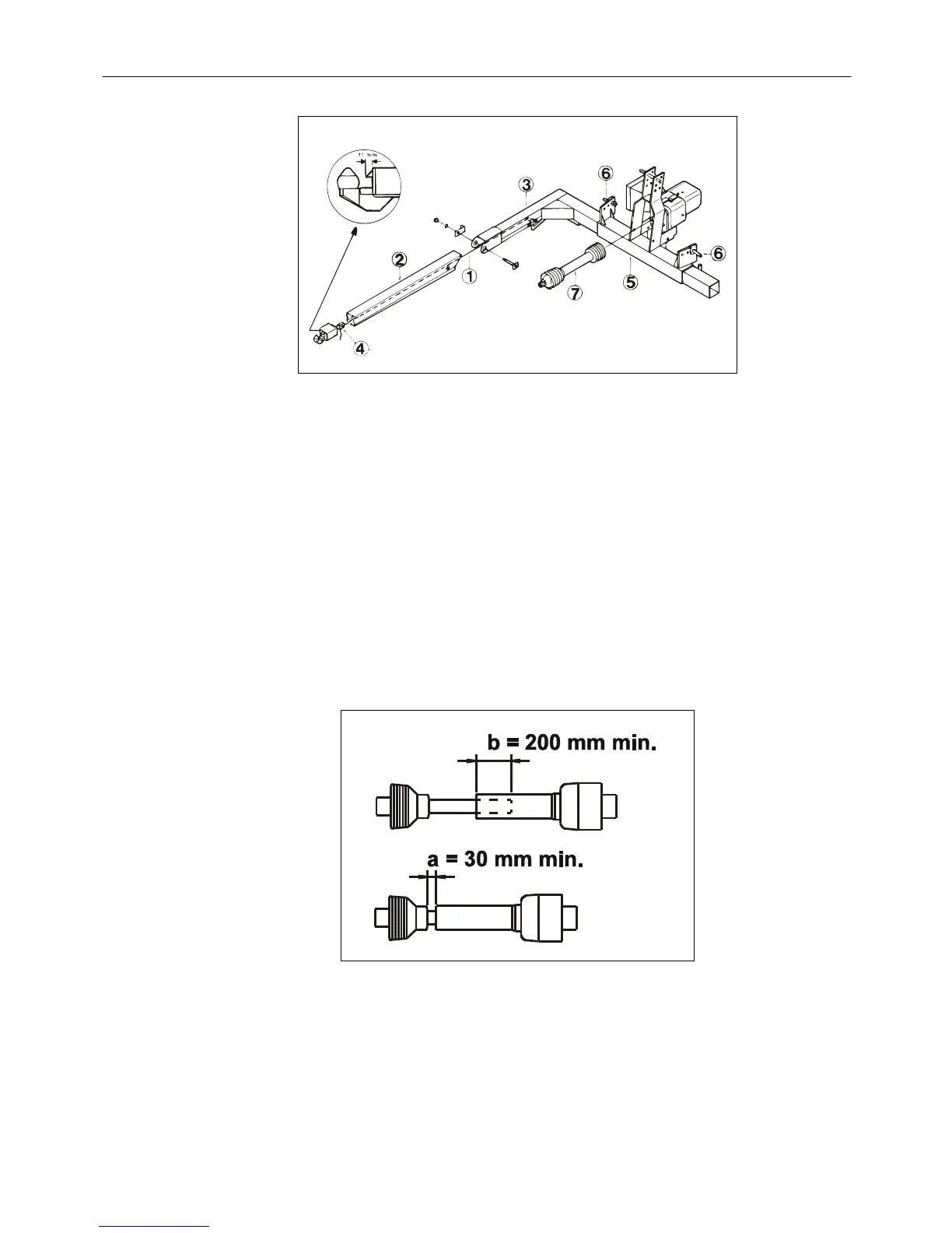
Fig. 2-7
Fig. 2-7 A. The wire 1 is led through the front arm.
B. The front arm 2 is mounted on the L-frame hoop 3.
C. The wire is fastened in pawl 4 and adjusted to correct length - 11 mm. The wire
must be so tight that the lower pawl 4 can be fully pulled in.
D. The suspension pins 6 are placed so that the precision chopper gets as close to
the tractor as possible. The rear hole at long link arms. The front hole at short
link arms.
E. The PTO shaft 7 is adjusted in length and mounted.
PR11-5017
Fig. 2-8
Fig. 2-8 The length of the PTO shaft is adjusted so that it: in working position has minimum
200 mm overlap. In no position is compressed more than the prescribed 30 mm in
order not to bottom the shaft. In the outmost position has minimum 200 mm overlap.
PIGB-138X-02 FC 855 0410
- 25 -