SECTION 2 - PROCEDURES
2-28 3121801
Tilt Sensor, JLG P/N 4000021:
TILT SENSOR REMOVAL:
NOTE: Refer to Figure 2-28., Tilt Sensor Removal for numbers in
parenthesis.
1. Disconnect the batteries.
2. Open the Ground Control Box to gain access to the Tilt
Sensor Assembly.
3. Remove the four Screws (3), Lockwashers (4), Standoff
Insulators (5), and Washers (6) to remove the Tilt Sensor
(1) and Sensor Mount (2) from the Ground Control Box.
4. The Tilt Sensor (1) can be removed from the Sensor
Mount (2) by removing the three Screws (7).
NOTE: Follow the above procedures in reverse order when install-
ing the tilt sensor assembly. After installing, be sure to cali-
brate the tilt sensor (refer to Section 2.18, Calibrations)
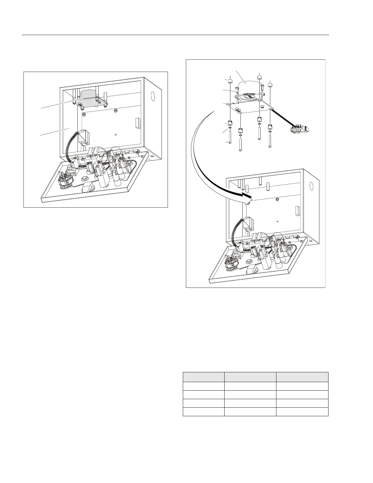
Figure 2-27. Tilt Sensor Location
1. Ground Control Box
2. Tilt Sensor Assembly (JLG P/N 1810140)
Table 2-9. Tilt Sensor Harness
Wire Color Function Connector Pin
Red VCC 1
Green PWMX 2
White PWMY 3
Black Ground 4
Figure 2-28. Tilt Sensor Removal
1. Tilt Sensor (JLG P/N 4000021)
2. Sensor Mount
3. Screw, 6-32 x 1
4. Lockwasher
5. Standoff Insulator
6. Washer, 0.313 x 0.250 Nylon
7. Screw, M3.5 x 0.6 x 10



 To Next Page