Electrical System
9.28
3507, 3508, 3509, 3512, 3513, 4007, 4008, 4009, 4012, 4013
c. Main Control Valve Solenoid Installation
1. Install the valve solenoid using new o-rings and
tighten the allenhead screws. Do not over tighten.
2. Connect the wire connector to the valve solenoid.
3. Connect the battery negative (-) cable to the battery
negative (-) terminal.
4. Start the machine and slowly move joystick to
engage function. If further troubleshooting is
required, refer to Section 9.5, “Electrical System
Schematics,” or Section 8.5, “Hydraulic Schematics.”
5. Close and secure the engine cover.
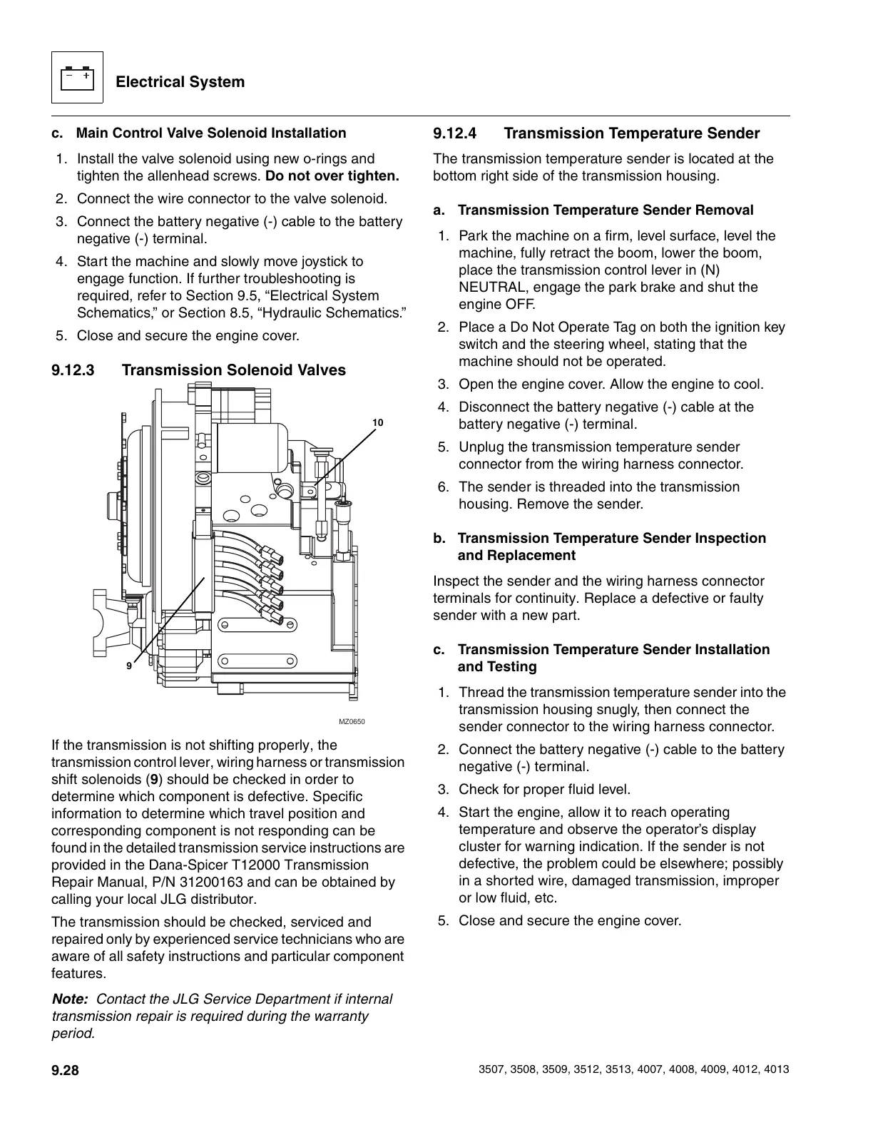
9.12.3 Transmission Solenoid Valves
If the transmission is not shifting properly, the
transmission control lever, wiring harness or transmission
shift solenoids (9) should be checked in order to
determine which component is defective. Specific
information to determine which travel position and
corresponding component is not responding can be
found in the detailed transmission service instructions are
provided in the Dana-Spicer T12000 Transmission
Repair Manual, P/N 31200163 and can be obtained by
calling your local JLG distributor.
The transmission should be checked, serviced and
repaired only by experienced service technicians who are
aware of all safety instructions and particular component
features.
Note: Contact the JLG Service Department if internal
transmission repair is required during the warranty
period.
9.12.4 Transmission Temperature Sender
The transmission temperature sender is located at the
bottom right side of the transmission housing.
a. Transmission Temperature Sender Removal
1. Park the machine on a firm, level surface, level the
machine, fully retract the boom, lower the boom,
place the transmission control lever in (N)
NEUTRAL, engage the park brake and shut the
engine OFF.
2. Place a Do Not Operate Tag on both the ignition key
switch and the steering wheel, stating that the
machine should not be operated.
3. Open the engine cover. Allow the engine to cool.
4. Disconnect the battery negative (-) cable at the
battery negative (-) terminal.
5. Unplug the transmission temperature sender
connector from the wiring harness connector.
6. The sender is threaded into the transmission
housing. Remove the sender.
b. Transmission Temperature Sender Inspection
and Replacement
Inspect the sender and the wiring harness connector
terminals for continuity. Replace a defective or faulty
sender with a new part.
c. Transmission Temperature Sender Installation
and Testing
1. Thread the transmission temperature sender into the
transmission housing snugly, then connect the
sender connector to the wiring harness connector.
2. Connect the battery negative (-) cable to the battery
negative (-) terminal.
3. Check for proper fluid level.
4. Start the engine, allow it to reach operating
temperature and observe the operator’s display
cluster for warning indication. If the sender is not
defective, the problem could be elsewhere; possibly
in a shorted wire, damaged transmission, improper
or low fluid, etc.
5. Close and secure the engine cover.
MZ0650
9
10
Courtesy of Crane.Market