Do you have a question about the JLG 3513 and is the answer not in the manual?
Provides ASTM fastener torque charts in English for various bolt sizes and grades.
Details specifications for travel speeds, hydraulic cylinders, electrical systems, and engine.
Provides instructions for boom removal and installation, emphasizing one section at a time.
Step-by-step procedure for removing boom sections and related components.
Procedure for removing the second boom section on 12 & 13M models.
Instructions for removing third section (12/13M) and second section (7/8/9M) booms.
Procedures for installing third section (12/13M) and second section (7/8/9M) booms.
Procedure for installing the second boom section on 12 & 13M models.
Detailed steps for installing the complete boom assembly, including cylinders and hoses.
Information on boom wear pads, including inspection, replacement, and lubrication.
Details on the quick switch system for easy attachment changes, including connection and removal.
Details various components within the cab, such as steering column, pedals, and controls.
Procedure for removing, installing, and testing the steering column and orbitrol valve.
Procedures for removal, installation, and testing of the service brake valve and pedal.
Instructions for removing, installing, and adjusting the throttle pedal.
Procedures for removing and installing the joystick assembly.
Procedures for removing and installing the parking brake components.
Procedure for removing the machine cab, emphasizing safety and proper handling.
Procedure for installing the machine cab, including securing and connecting components.
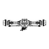
Covers axle serial number plates, specifications, internal service, and maintenance.
Outlines the procedure for removing front and rear axle assemblies, ensuring cleanliness.
Troubleshooting common problems related to axle noise and drive shaft issues.
Covers drive shaft inspection, maintenance, removal, cleaning, and installation.
Procedure for removing drive shafts, emphasizing marking components for reinstallation.
Steps for cleaning and drying drive shaft parts using approved methods.
Procedure for installing drive shafts, including torque specifications and alignment.
Recommendations for replacement tires and safety warnings about mismatched tires.
Procedure for inspecting brake discs on front and rear axles.
Provides instructions for transmission replacement, emphasizing safety and cleanliness.
Step-by-step procedure for removing the transmission, including draining and disconnecting components.
References Dana Spicer Manual for internal transmission repair and component transfer.
Procedure for installing the transmission, including torque specifications and fluid filling.
Provides solutions for common transmission operational problems.
Addresses issues like no engagement, low pump flow, clutch pressure, lack of power, and overheating.
Covers radiator pressure cap, thermostat replacement, and radiator/oil cooler replacement.
Guidelines for diagnosing and replacing a faulty thermostat.
Procedures for removing and installing the radiator, oil cooler, and coolant heater.
Covers diesel fuel usage, fuel tank maintenance, and post-service procedures.
Procedures for fuel tank removal, disassembly, cleaning, and installation.
Covers removal and installation of the engine exhaust system components.
Instructions for removing and installing the air cleaner assembly.
Procedures for engine removal, disassembly, inspection, service, and installation.
Step-by-step procedure for removing the engine, including disconnecting all systems.
References Perkins service manual for detailed engine disassembly, inspection, and service procedures.
Procedure for installing the engine, aligning components, and connecting systems.
Procedures for removing and installing the engine drive plates.
Troubleshooting guide for common engine problems, with possible causes and remedies.
Introduces the JLG Pressure Test Kit for hydraulic system maintenance and troubleshooting.
Covers hydraulic function pressures, checks, and adjustments.
Covers draining, filling, removal, and installation of the hydraulic oil reservoir.
Procedures for removing and installing the hydraulic oil reservoir.
Details pump description, failure analysis, and replacement procedures.
Procedures for removing, installing, and testing the hydraulic system pump.
Step-by-step procedure for removing the hydraulic pump.
Procedure for installing the hydraulic pump, including alignment and torque specifications.
Details main control valve, service brake valve, steer valves, and ERS control valve.
Covers removal, disassembly, cleaning, inspection, assembly, installation, and testing.
Steps for removing the main control valve and bracket from the frame.
Procedure for disassembling individual sections of the main control valve.
Steps for installing the main control valve onto the bracket and priming it.
Procedures for removing, installing, and testing the service brake valve.
Steps for removing the service brake valve from the steering column support.
Procedure for installing the service brake valve, including alignment and lubrication.
Describes the steer select valve and provides removal, disassembly, and testing procedures.
Procedures for removing and installing the ERS Control Valve Assembly (13M Platform machines).
Covers cylinder removal, disassembly, cleaning, inspection, assembly, installation, and torque specs.
Steps for removing hydraulic cylinders, including pressure relief and hose disconnection.
Procedure for disassembling hydraulic cylinders, including piston and head gland removal.
Procedure for assembling hydraulic cylinders using proper tools and seal kits.
Steps for installing hydraulic cylinders, including greasing, alignment, and hose connection.
Provides torque specifications for lift, extend/retract, tilt, compensation, sway, and outrigger cylinders.
Torque specifications for lift cylinder piston, head, and set screw for various models.
Torque specifications for extend/retract cylinder piston, head, plug, and set screw.
Torque specifications for tilt cylinder piston, head, nut, and set screw.
Torque specifications for compensation cylinder piston, head, nut, and set screw.
Torque specifications for sway cylinder piston, head, plug, nut, and set screw.
Locates fuse and relay panels in the cab and engine compartment.
Covers starter testing, circuit checks, removal, installation, and maintenance.
Checks for alternator operation and provides procedures for alternator removal and installation.
Describes load moment indicator, sensor, and back-up alarm.
Covers sensor removal, installation, and calibration procedures.
Covers windshield and rear window wiper motor and washer system procedures.
Covers removal, disassembly, and installation of cab heater controls.
Details fuel shut-off solenoid, main control valve solenoids, and transmission solenoids.
Covers removal, disassembly, installation, and testing of analog gauges.
| Brand | JLG |
|---|---|
| Model | 3513 |
| Category | Construction Equipment |
| Language | English |