4.9
3507, 3508, 3509, 3512, 3513, 4007, 4008, 4009, 4012, 4013
Cab and Covers
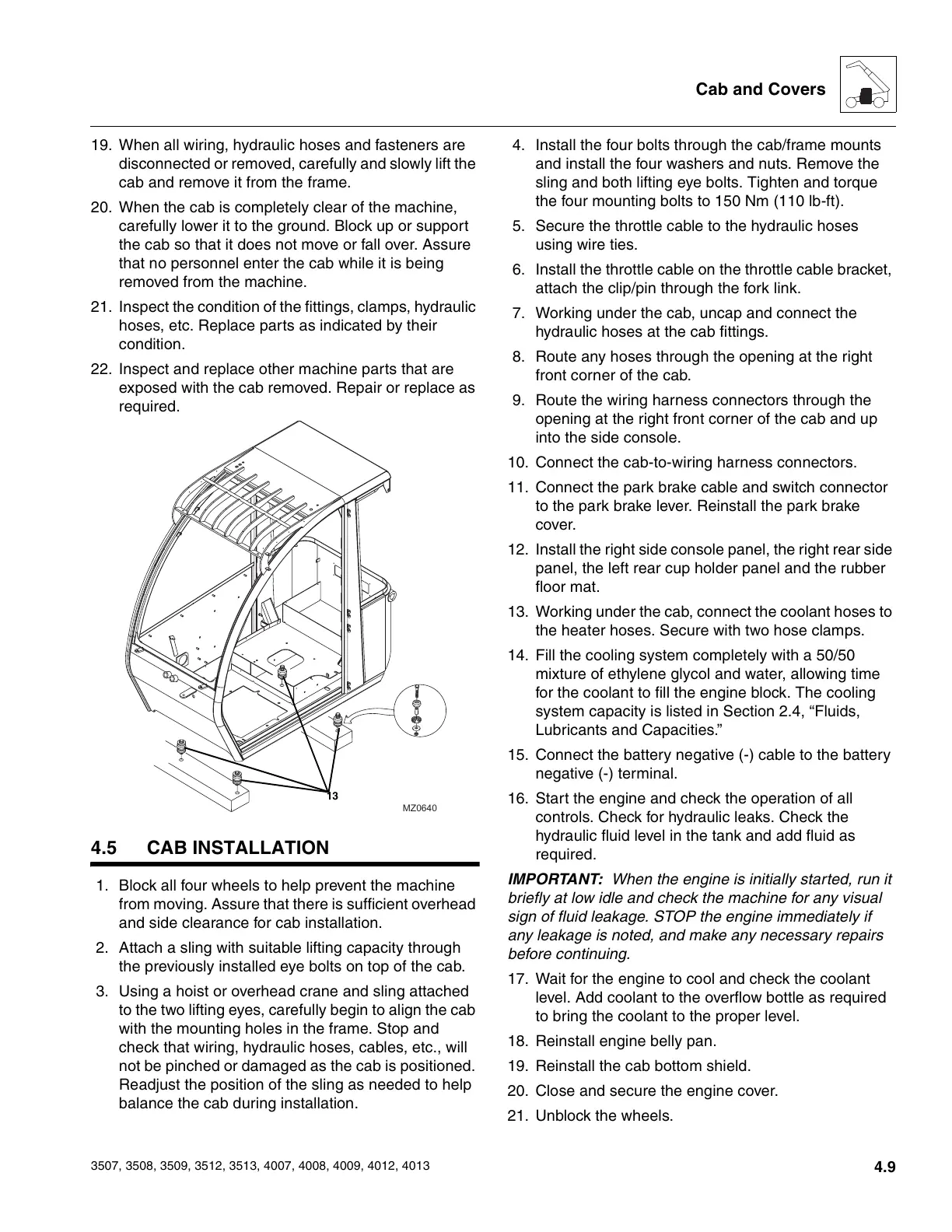
19. When all wiring, hydraulic hoses and fasteners are
disconnected or removed, carefully and slowly lift the
cab and remove it from the frame.
20. When the cab is completely clear of the machine,
carefully lower it to the ground. Block up or support
the cab so that it does not move or fall over. Assure
that no personnel enter the cab while it is being
removed from the machine.
21. Inspect the condition of the fittings, clamps, hydraulic
hoses, etc. Replace parts as indicated by their
condition.
22. Inspect and replace other machine parts that are
exposed with the cab removed. Repair or replace as
required.
4.5 CAB INSTALLATION
1. Block all four wheels to help prevent the machine
from moving. Assure that there is sufficient overhead
and side clearance for cab installation.
2. Attach a sling with suitable lifting capacity through
the previously installed eye bolts on top of the cab.
3. Using a hoist or overhead crane and sling attached
to the two lifting eyes, carefully begin to align the cab
with the mounting holes in the frame. Stop and
check that wiring, hydraulic hoses, cables, etc., will
not be pinched or damaged as the cab is positioned.
Readjust the position of the sling as needed to help
balance the cab during installation.
4. Install the four bolts through the cab/frame mounts
and install the four washers and nuts. Remove the
sling and both lifting eye bolts. Tighten and torque
the four mounting bolts to 150 Nm (110 lb-ft).
5. Secure the throttle cable to the hydraulic hoses
using wire ties.
6. Install the throttle cable on the throttle cable bracket,
attach the clip/pin through the fork link.
7. Working under the cab, uncap and connect the
hydraulic hoses at the cab fittings.
8. Route any hoses through the opening at the right
front corner of the cab.
9. Route the wiring harness connectors through the
opening at the right front corner of the cab and up
into the side console.
10. Connect the cab-to-wiring harness connectors.
11. Connect the park brake cable and switch connector
to the park brake lever. Reinstall the park brake
cover.
12. Install the right side console panel, the right rear side
panel, the left rear cup holder panel and the rubber
floor mat.
13. Working under the cab, connect the coolant hoses to
the heater hoses. Secure with two hose clamps.
14. Fill the cooling system completely with a 50/50
mixture of ethylene glycol and water, allowing time
for the coolant to fill the engine block. The cooling
system capacity is listed in Section 2.4, “Fluids,
Lubricants and Capacities.”
15. Connect the battery negative (-) cable to the battery
negative (-) terminal.
16. Start the engine and check the operation of all
controls. Check for hydraulic leaks. Check the
hydraulic fluid level in the tank and add fluid as
required.
IMPORTANT: When the engine is initially started, run it
briefly at low idle and check the machine for any visual
sign of fluid leakage. STOP the engine immediately if
any leakage is noted, and make any necessary repairs
before continuing.
17. Wait for the engine to cool and check the coolant
level. Add coolant to the overflow bottle as required
to bring the coolant to the proper level.
18. Reinstall engine belly pan.
19. Reinstall the cab bottom shield.
20. Close and secure the engine cover.
21. Unblock the wheels.
MZ0640
13
Courtesy of Crane.Market