5.11
3507, 3508, 3509, 3512, 3513, 4007, 4008, 4009, 4012, 4013
Axles, Drive Shafts, Wheels and Tires
5.5.2 Installing Wheel and Tire Assembly
onto Machine
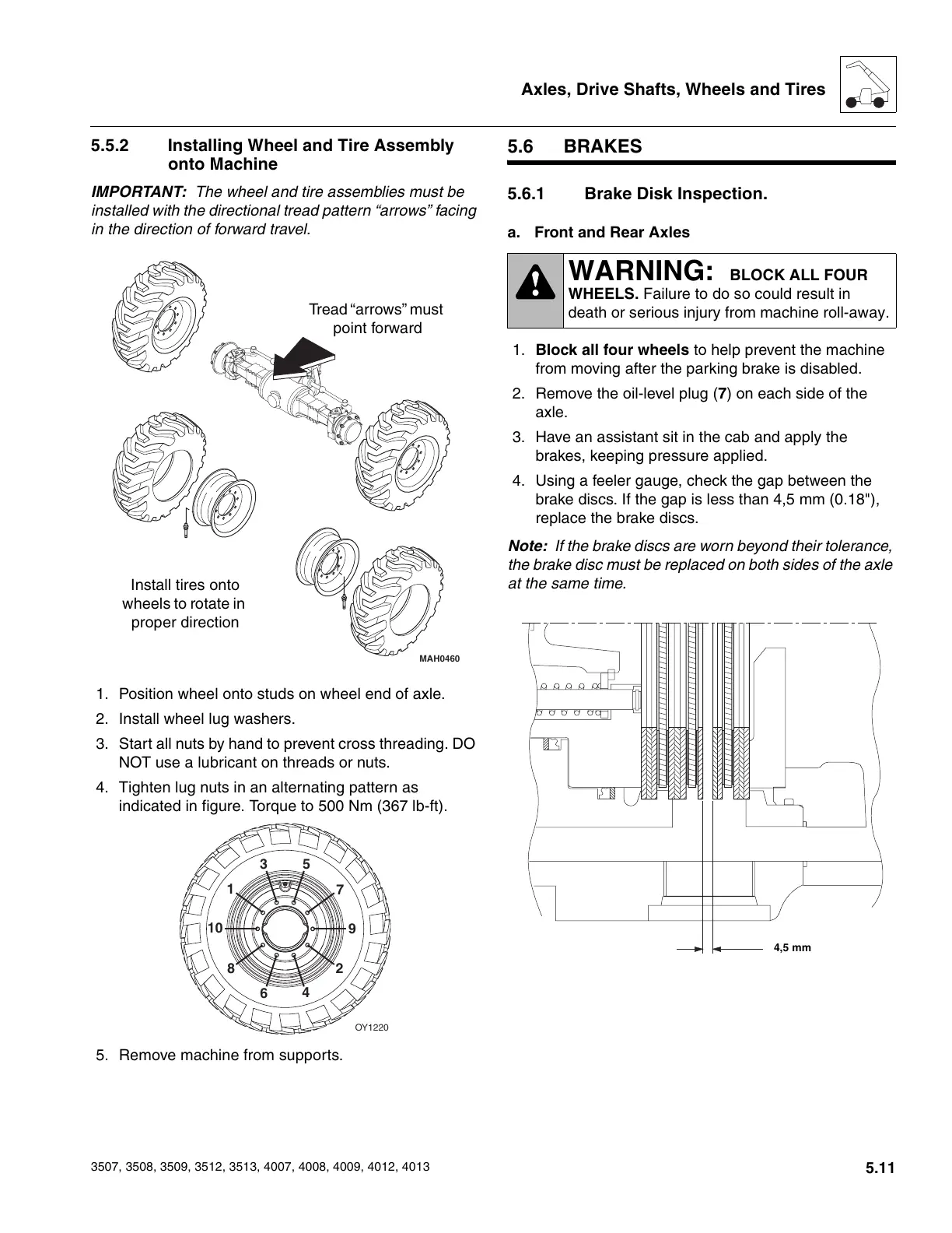
IMPORTANT: The wheel and tire assemblies must be
installed with the directional tread pattern “arrows” facing
in the direction of forward travel.
1. Position wheel onto studs on wheel end of axle.
2. Install wheel lug washers.
3. Start all nuts by hand to prevent cross threading. DO
NOT use a lubricant on threads or nuts.
4. Tighten lug nuts in an alternating pattern as
indicated in figure. Torque to 500 Nm (367 lb-ft).
5. Remove machine from supports.
5.6 BRAKES
5.6.1 Brake Disk Inspection.
a. Front and Rear Axles
1. Block all four wheels to help prevent the machine
from moving after the parking brake is disabled.
2. Remove the oil-level plug (7) on each side of the
axle.
3. Have an assistant sit in the cab and apply the
brakes, keeping pressure applied.
4. Using a feeler gauge, check the gap between the
brake discs. If the gap is less than 4,5 mm (0.18"),
replace the brake discs.
Note: If the brake discs are worn beyond their tolerance,
the brake disc must be replaced on both sides of the axle
at the same time.
MAH0460
Tread “arrows” must
point forward
Install tires onto
wheels to rotate in
proper direction
OY1220
1
2
3
4
5
6
7
8
9
10
WARNING: BLOCK ALL FOUR
WHEELS. Failure to do so could result in
death or serious injury from machine roll-away.
4,5 mm
Courtesy of Crane.Market