Cab and Covers
4.2
3507, 3508, 3509, 3512, 3513, 4007, 4008, 4009, 4012, 4013
4.1 OPERATOR’S CAB AND COVERS
COMPONENT TERMINOLOGY
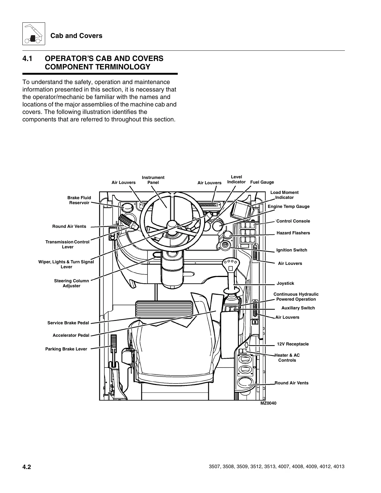
To understand the safety, operation and maintenance
information presented in this section, it is necessary that
the operator/mechanic be familiar with the names and
locations of the major assemblies of the machine cab and
covers. The following illustration identifies the
components that are referred to throughout this section.
Air Louvers
Air Louvers
Instrument
Panel
Level
Indicator
Fuel Gauge
Load Moment
Indicator
Engine Temp Gauge
Control Console
Hazard Flashers
Ignition Switch
Air Louvers
Joystick
Continuous Hydraulic
Powered Operation
Auxiliary Switch
Air Louvers
12V Receptacle
Heater & AC
Controls
Round Air Vents
Round Air Vents
Brake Fluid
Reservoir
Transmission Control
Lever
Wiper, Lights & Turn Signal
Lever
Steering Column
Adjuster
Service Brake Pedal
Accelerator Pedal
Parking Brake Lever
MZ0040
Courtesy of Crane.Market