Hydraulic System
8.18
3507, 3508, 3509, 3512, 3513, 4007, 4008, 4009, 4012, 4013
8.9.3 Cylinder Cleaning Instructions
1. Discard all seals, back-up rings and o-rings. Replace
with new items from complete seal kits to help
ensure proper cylinder function.
2. Clean all metal parts with an approved cleaning
solvent such as trichlorethylene. Carefully clean
cavities, grooves, threads, etc.
Note: If a white powdery residue is present on threads
and parts, it can be removed. Clean the residue away
with a soft brass wire brush prior to reassembly, and
wipe with loctite cleaner before reinstallation.
8.9.4 Cylinder Inspection
1. Inspect internal surfaces and all parts for wear,
damage, etc. If the inner surface of the tube does not
display a smooth finish, or is scored or damaged in
any way, replace the tube.
2. Remove light scratches on the piston, rod or inner
surface of the tube with a 400-600 grit emery cloth.
Use the emery cloth in a rotary motion to polish out
and blend the scratch(es) into the surrounding
surface.
3. Check the piston rod assembly for run-out. If the rod
is bent, it must be replaced.
8.9.5 General Cylinder Assembly
1. Use the proper tools for specific installation tasks.
Clean tools are required for assembly.
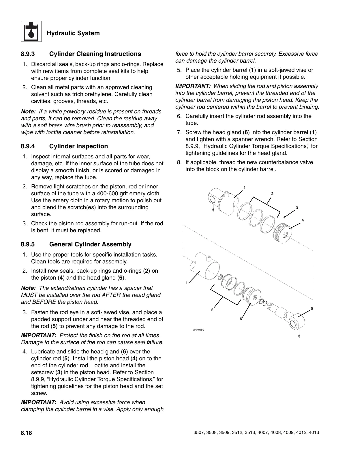
2. Install new seals, back-up rings and o-rings (2) on
the piston (4) and the head gland (6).
Note: The extend/retract cylinder has a spacer that
MUST be installed over the rod AFTER the head gland
and BEFORE the piston head.
3. Fasten the rod eye in a soft-jawed vise, and place a
padded support under and near the threaded end of
the rod (5) to prevent any damage to the rod.
IMPORTANT: Protect the finish on the rod at all times.
Damage to the surface of the rod can cause seal failure.
4. Lubricate and slide the head gland (6) over the
cylinder rod (5). Install the piston head (4) on to the
end of the cylinder rod. Loctite and install the
setscrew (3) in the piston head. Refer to Section
8.9.9, “Hydraulic Cylinder Torque Specifications,” for
tightening guidelines for the piston head and the set
screw.
IMPORTANT: Avoid using excessive force when
clamping the cylinder barrel in a vise. Apply only enough
force to hold the cylinder barrel securely. Excessive force
can damage the cylinder barrel.
5. Place the cylinder barrel (1) in a soft-jawed vise or
other acceptable holding equipment if possible.
IMPORTANT: When sliding the rod and piston assembly
into the cylinder barrel, prevent the threaded end of the
cylinder barrel from damaging the piston head. Keep the
cylinder rod centered within the barrel to prevent binding.
6. Carefully insert the cylinder rod assembly into the
tube.
7. Screw the head gland (6) into the cylinder barrel (1)
and tighten with a spanner wrench. Refer to Section
8.9.9, “Hydraulic Cylinder Torque Specifications,” for
tightening guidelines for the head gland.
8. If applicable, thread the new counterbalance valve
into the block on the cylinder barrel.
MAH0160
1
4
3
2
6
5
2
1
Courtesy of Crane.Market