Axles, Drive Shafts, Wheels and Tires
5.4
3507, 3508, 3509, 3512, 3513, 4007, 4008, 4009, 4012, 4013
5.3.5 Axle Removal
The front and rear axle assemblies differ in that the front
axle assembly is equipped with a parking brake
mechanism and a limited-slip feature; the rear axle has
neither. The following steps outline a typical axle removal
procedure, suitable for either the front or the rear axle
assembly.
Cleanliness is extremely important. Before attempting to
remove the axle, thoroughly clean the machine. Avoid
spraying water or cleaning solution on the outrigger
solenoids and other electrical components. If using a
steam cleaner, seal all openings before steam cleaning.
IMPORTANT: Clear the work area of all debris,
unnecessary personnel, etc. Allow sufficient space to
raise the machine and to remove the axle.
1. Park the machine on a firm, level surface, level the
machine, fully retract the boom, lower the boom,
place the transmission control lever in
(N) NEUTRAL, engage the park brake and shut the
engine OFF.
2. Place a Do Not Operate Tag on both the ignition key
switch and steering wheel, stating that the machine
should not be operated.
3. Open the engine cover. Allow the system fluids to
cool.
4. Disconnect the battery negative (-) cable at the
battery negative (-) terminal.
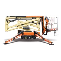
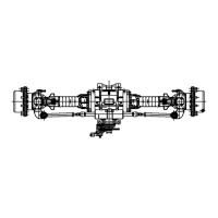
5. If the axle will be disassembled after removal, place
a suitable receptacle under the axle (1) and wheel
hubs drain plugs (2). Remove the drain plugs and
allow the axle oil to drain into the receptacle.
Transfer the used axle oil into a suitable covered
container, and label the container as "Used Oil".
Dispose of used oil at an approved recycling facility.
6. Label, disconnect and cap the steering and brake
lines at the axle. Wipe up any spilled oil.
7. Block the front and rear of both tires on the axle that
is not being removed. Ensure that the machine will
remain in place during axle removal before
proceeding.
8. Raise the machine using a suitable jack or hoist.
Place suitable supports under both sides of the
frame and lower the machine onto the supports.
Ensure that the machine will remain in place during
axle removal.
9. Support the axle that is being removed with a suitable
jack, hoist or overhead crane and sling. DO NOT
raise the axle or the machine.
10. Mark and remove both wheel and tire assemblies
from the axle that is being removed. (Refer to
Section 5.5.1, “Removing Wheel and Tire Assembly
from Machine.”)
11. Remove the drive shaft assembly. Refer to Section
5.4.3, “Drive Shaft Removal.”
12. On the front axle, remove the hardware securing the
sway cylinder or bar (not necessary on machines
with fixed axles before S/N 1160000798). Tap the
mount pin out, and move the cylinder or bar to
prevent it from interfering with axle removal.
13. Remove the park brake cable from the front axle.
14. Remove the bolts and locknuts securing the axle to
the frame.
15. Remove the axles from the machine using the jack,
hoist or overhead crane and sling supporting the
axle. DO NOT raise or otherwise disturb the machine
while removing the axle. Balance the axle and
prevent it from tipping, turning or falling while
removing it from beneath the machine. Place the
axle on a suitable support or holding stand.
MZ103
1
MZ1520
2
Courtesy of Crane.Market