Electrical System
9.4
3507, 3508, 3509, 3512, 3513, 4007, 4008, 4009, 4012, 4013
9.2 SPECIFICATIONS
Electrical system specifications are listed in Section 2,
“General Information and Specifications.”
9.3 SERVICE WARNING
9.4 FUSES AND RELAYS
9.4.1 Cab
For access to the fuse and relay panel, remove the
screw (2) securing the right side console access
panel (3) to the cab. The fuses and sealed 12-volt relays
are mounted under the right side console access panel.
The fuse and relay panels are part of the cab harness.
9.4.2 Engine Compartment
The fuse and relay bar is located on the frame directly
above the engine. The fuse and relay bar contains the lift
pump and glow plug fuses (4), starter relay (5), glow plug
relay (6) and lift pump relay (7). To remove the relays
from inside the engine compartment, remove the
mounting screws and washers. When re-installing the
relays, torque the mounting hardware to 7-12,5 Nm
(62-110 lb-in).
Note: On machines before S/N 1160000358, the fuse
and relay bar is not present. Only the starter relay is
mounted on the frame above the engine.
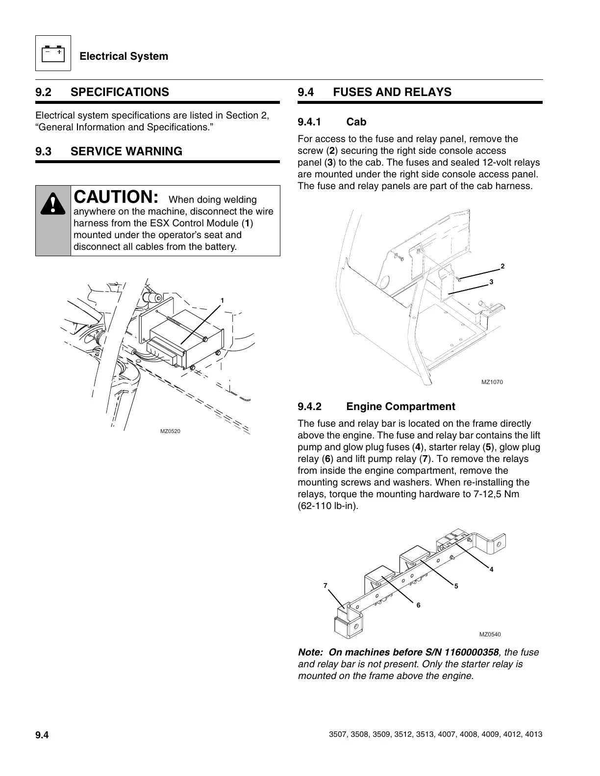
CAUTION: When doing welding
anywhere on the machine, disconnect the wire
harness from the ESX Control Module (1)
mounted under the operator’s seat and
disconnect all cables from the battery.
MZ0520
1
MZ1070
3
2
MZ0540
4
5
6
7
Courtesy of Crane.Market