Engine: Perkins 1104-42 & 1104-42T
7.8
3507, 3508, 3509, 3512, 3513, 4007, 4008, 4009, 4012, 4013
d. Assembly
The fuel level indicator can be removed and reused on
the new replacement tank. Dispose of the old tank
according to local regulations concerning hazardous
materials disposal.
e. Inspection
Note: If a leak is suspected in the fuel tank, contact your
local JLG distributor.
1. Inspect the fuel tank thoroughly for any cracks,
slices, leaks or other damage.
2. Plug all openings except one elbow fitting. Install the
elbow fitting, and apply approximately 7-10 kPa
(1-1.5 psi) of air pressure through the elbow. Check
the tank for leaks by applying a soap solution to the
exterior and look for bubbles to appear at the
cracked or damaged area.
f. Fuel Tank Installation
1. Set fuel tank between frame rails.
2. Install the fuel tank strap over the fuel tank.
3. Install the fuel sender with new gasket into the fuel
tank and secure with screws. Tighten to 5 Nm
(3.6 lb-ft). DO NOT overtighten.
4. Connect the fuel supply hose and return line hose to
the tank. Secure with clamps and tighten to 25 Nm
(18 lb-ft)
5. Install the wire harness connections to the fuel
sender.
6. Fill the fuel tank according to specifications. Refer to
Section 2.4, “Fluids, Lubricants and Capacities.”
7. Check fuel tank for leaks.
8. Install the boom. Refer to Section 3.3.6, “Boom
Installation.”
9. Connect the battery negative (-) cable to the battery
negative (-) terminal.
10. Close and secure the engine cover.
7.6.3 After Fuel System Service
1. Drain and flush the fuel tank if it was contaminated.
2. Vent air from the fuel system in accordance with the
instructions found in the appropriate Operation &
Safety Manual.
3. Fill the fuel tank with fresh, clean diesel fuel as required.
7.7 ENGINE EXHAUST SYSTEM
7.7.1 Exhaust System Removal
1. Park the machine on a firm, level surface, level the
machine, fully retract the boom, lower the boom,
place the transmission control lever in
(N) NEUTRAL, engage the park brake and shut the
engine OFF.
2. Place a Do Not Operate Tag on both the ignition key
switch and steering wheel, stating that the machine
should not be operated.
3. Open the engine cover. Allow the engine to cool.
4. Disconnect the battery negative (-) cable from the
battery negative (-) terminal.
5. Remove the belly pan.
6. Loosen and remove the mounting hardware for the
exhaust pipe at the exhaust manifold. Replace the
hardware if damaged.
7. Disconnect and remove the clamp attaching the
exhaust pipe to the frame.
8. Disconnect and remove the clamp connecting the
muffler to the exhaust pipe.
9. Disconnect and remove the clamp connecting the
tail pipe to the muffler and remove the tail pipe.
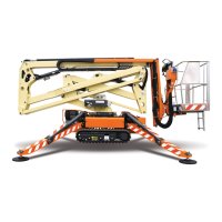
10. Loosen and remove the two bolts at the front and
one bolt at the rear of the muffler, and remove the
muffler.
7.7.2 Exhaust System Installation
Note: Keep all clamps loosened until entire exhaust
system is in place.
1. Install the exhaust pipe with a new seal to the
exhaust manifold.
2. Install the exhaust pipe clamp under the engine.
3. Install the muffler to the exhaust pipe and bolt the
muffler to the side of the frame.
4. Install the clamp securing the muffler to the exhaust
pipe.
MZ0110
Courtesy of Crane.Market