Cab and Covers
4.4
3507, 3508, 3509, 3512, 3513, 4007, 4008, 4009, 4012, 4013
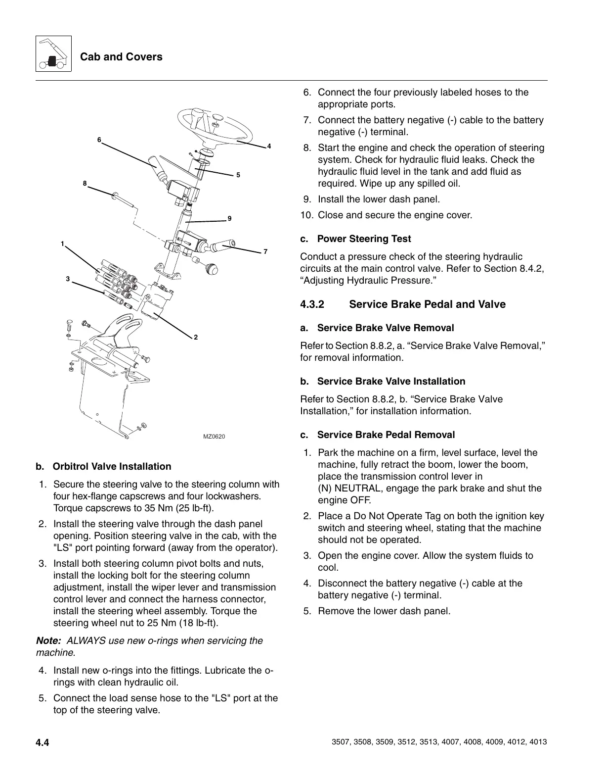
b. Orbitrol Valve Installation
1. Secure the steering valve to the steering column with
four hex-flange capscrews and four lockwashers.
Torque capscrews to 35 Nm (25 lb-ft).
2. Install the steering valve through the dash panel
opening. Position steering valve in the cab, with the
"LS" port pointing forward (away from the operator).
3. Install both steering column pivot bolts and nuts,
install the locking bolt for the steering column
adjustment, install the wiper lever and transmission
control lever and connect the harness connector,
install the steering wheel assembly. Torque the
steering wheel nut to 25 Nm (18 lb-ft).
Note: ALWAYS use new o-rings when servicing the
machine.
4. Install new o-rings into the fittings. Lubricate the o-
rings with clean hydraulic oil.
5. Connect the load sense hose to the "LS" port at the
top of the steering valve.
6. Connect the four previously labeled hoses to the
appropriate ports.
7. Connect the battery negative (-) cable to the battery
negative (-) terminal.
8. Start the engine and check the operation of steering
system. Check for hydraulic fluid leaks. Check the
hydraulic fluid level in the tank and add fluid as
required. Wipe up any spilled oil.
9. Install the lower dash panel.
10. Close and secure the engine cover.
c. Power Steering Test
Conduct a pressure check of the steering hydraulic
circuits at the main control valve. Refer to Section 8.4.2,
“Adjusting Hydraulic Pressure.”
4.3.2 Service Brake Pedal and Valve
a. Service Brake Valve Removal
Refer to Section 8.8.2, a. “Service Brake Valve Removal,”
for removal information.
b. Service Brake Valve Installation
Refer to Section 8.8.2, b. “Service Brake Valve
Installation,” for installation information.
c. Service Brake Pedal Removal
1. Park the machine on a firm, level surface, level the
machine, fully retract the boom, lower the boom,
place the transmission control lever in
(N) NEUTRAL, engage the park brake and shut the
engine OFF.
2. Place a Do Not Operate Tag on both the ignition key
switch and steering wheel, stating that the machine
should not be operated.
3. Open the engine cover. Allow the system fluids to
cool.
4. Disconnect the battery negative (-) cable at the
battery negative (-) terminal.
5. Remove the lower dash panel.
MZ0620
4
6
7
1
2
8
3
9
5
Courtesy of Crane.Market