·39·
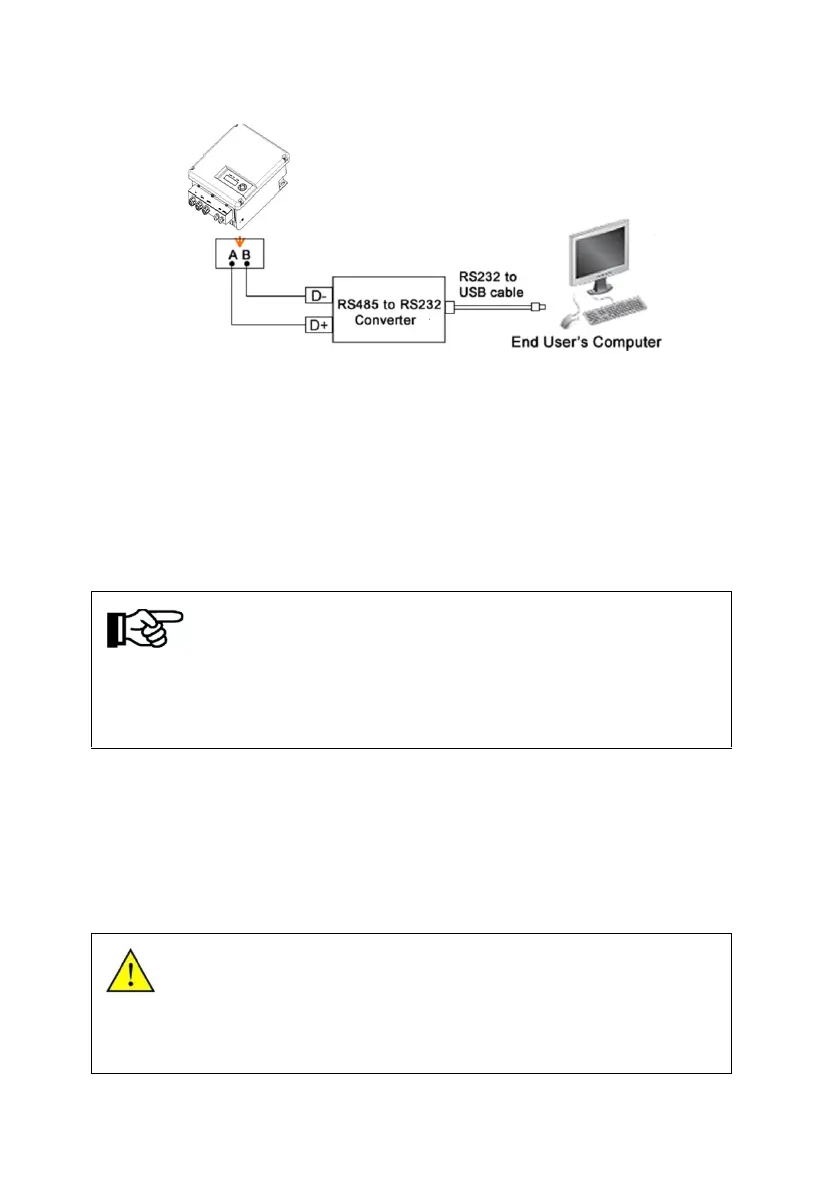
Figure6-11 Diagram of single communication wiring
The wiring diagram is schematic diagram, just take HEXIN converting module
as an example. If the user choose other converter, need according to the
converter‘s instructions, wiring the inverter’s A, B wires to the converter’s
correct terminal.
Please refer to “Inverter Management System User Manual” for the
corresponding monitoring software settings, after completing the wire
connection.
Notice!
The monitoring software is optional, when choose this function, “Inverter
Management System User Manual” can be found from the
accompanying CD.
The inverter is supplied with default address "10".
9.7.2 GPRS Communication
Notice:More information about the communication module, please refer to the
User and Installation Manual For GPRS.
9.8 Disassembling
9.8.1Safety Instruction
Warning!
Before disassembling the inverter:
● Turn off the DC switch.
● Waiting for a few minutes till ensure the inverter is uncharged.