·37·
A
C
D
S
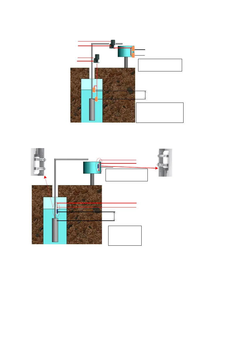
A:the Installation location of
overflow high water level sensor.
B:the Installation location of
overflow low water level sensor.
1. C:the Installation location of pump
dryed high water level sensor.
2. D:Pump outlet,the Installation
location of pump dryed low water
level sensor.
3. S about 1-3 m .
B
To Wa ter le vel
sen sor connecto r
B1 connect To SY
B2 connect to COM
A2 connect to COM
A1 connect to DG
Figure6-8 The installation figure of Sensor A
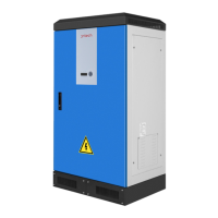
If you selected water level sensor B, then water sensor installation method is
shown below:
connect to COM
connect to DG
connect to COM
connect to SY
A:the Installation location of
overflow water level
sensor.
1. B:the Installation
location of pump dryed
water level sensor.
2. C:Pump outlet.
3. S about 1-3 m .
A
B
C
S
For dry protection, the end with cable
of sensor should be upwards
For over-
flow protection, the end with cable of
sensor should be downwards.
Figure6-9 The installation figure of Sensor B
9.7 Communication Connection
9.7.1 RS485 Communication
When the inverter communicates with a single machine, the communication
between the inverter and the monitoring equipment can be connected through
the communication cable. The COM outside the inverter is the remote
communication terminal, and the output terminal wire is connected to the