·74·
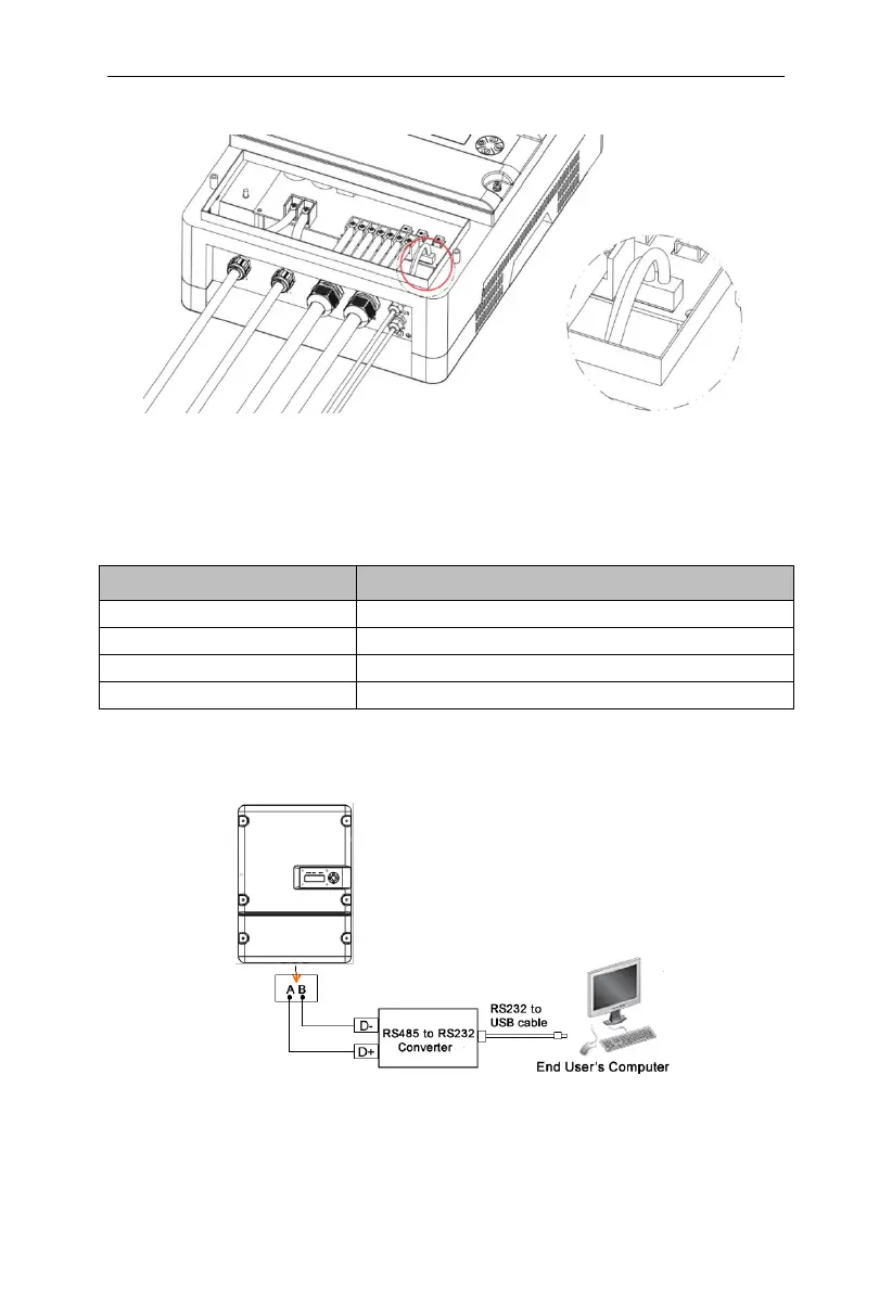
Figure6-10 Communication connection terminal
The com part of the machine panel and the water level sensor use the same
terminal block, and the pin definitions are shown in the table below:
Table 6-5 COM terminal pin definition on machine panel
RS485 communication port A.
RS485 communication port B.
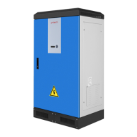
The following diagram guide you to connect a single inverter to monitoring
equipment.
Figure6-11 Diagram of single communication wiring
The wiring diagram is schematic diagram, just take HEXIN converting module