QUANTUM™ HD COMPRESSOR CONTROL PANEL
MAINTENANCE
090.040-M (MAR 12)
Page 27
to feed all signals to the following connec-
tors. If the auxiliary Analog or Digital Board
is not present then a jumper plug (see Rec-
ommended Spare Parts List) must be in-
stalled to daisy chain the signals.
The most common symptom that is exhibited by a
low +5 Vdc voltage to the Digital Boards is an alarm
message that reads Digital Board Reset Shutdown.
ACTIVE LED
The Digital Boards have an Active LED indicator on
the board that blinks when the board’s software is
running.
If the Active LED is not blinking, check to ensure that
the EPROM is installed properly. The EPROM is lo-
cated in chip slot U8, next to the power connector.
DIGITAL INPUTS
A Digital Input is the portion of the hardware that
allows devices such as limit switches, relay contacts,
and level switches, to interface with the Quantum™
HD. The software program within the Quantum™
HD is constantly looking at these Input channels, via
communications, and based upon whether a control
voltage is present or not, will provide the neces-
sary control for an associated Output channel. For
instance, if a control voltage is present on the Oil
Level Sensor input, the software will determine that
the Separator has suffi cient oil level for the oil heat-
ers to be energized (if the temperature of the oil is
also sensed to be low. Temperature sensing will be
discussed in the Analog Input section).
There are two possible varieties of Digital Input mod-
ules used on standard compressor control packages.
One is for 120 Volt controls, and the other is for 230
volt controls. Both of these module styles are yel-
low in color. A side profi le of these modules is shown
below:
5 4 3
COM OUT VDC
2
1
90-140VAC
120 VAC
5 4 3
COM OUT VDC
2
1
180-280VAC
240 VAC
230 VAC
These Input modules, can be identifi ed as to their
operating voltage by looking at either the side, as
shown above, or from the top. You will notice the
module operating voltage printed on the top, and the
voltage range printed on the side.
Never plug a 120 Volt Input module into a 230 Volt
system, and vice-versa. Never plug an Output module
into a position designated for an Input module.
You will notice that when a module is plugged into
the Digital board, there is a fuse located directly ad-
jacent to the module. This fuse is of the pluggable
variety, and must be plugged into the IN position for
an Input module.
DIGITAL OUTPUTS
A Digital Output is the portion of the hardware that
the Q5 is to control (energize). These devices include
solenoids, relay coils, and heaters to be energized,
based upon the logic within the Quantum™ HD soft-
ware program.
There is one variety of Digital Output modules used
on standard compressor control packages. This one
module will handle both 120 Volt controls, and 230
volt controls. This module is black in color. A side
profi le of this module is shown below:
4 3
3-8 VDC
2
1
3A 280VAC
120/240 VAC
120/230 VAC
Although this Output module is labeled as 280 VAC on
the top, and on the side, it can be used on both 120
and 230 volt applications.
Never plug an Input module into a position designat-
ed for an Output module.
You will notice that when a module is plugged into
the Digital Board, there is a fuse located directly ad-
jacent to the module. This fuse is of the pluggable
variety, and must be plugged into the OUT position
for an Output module.
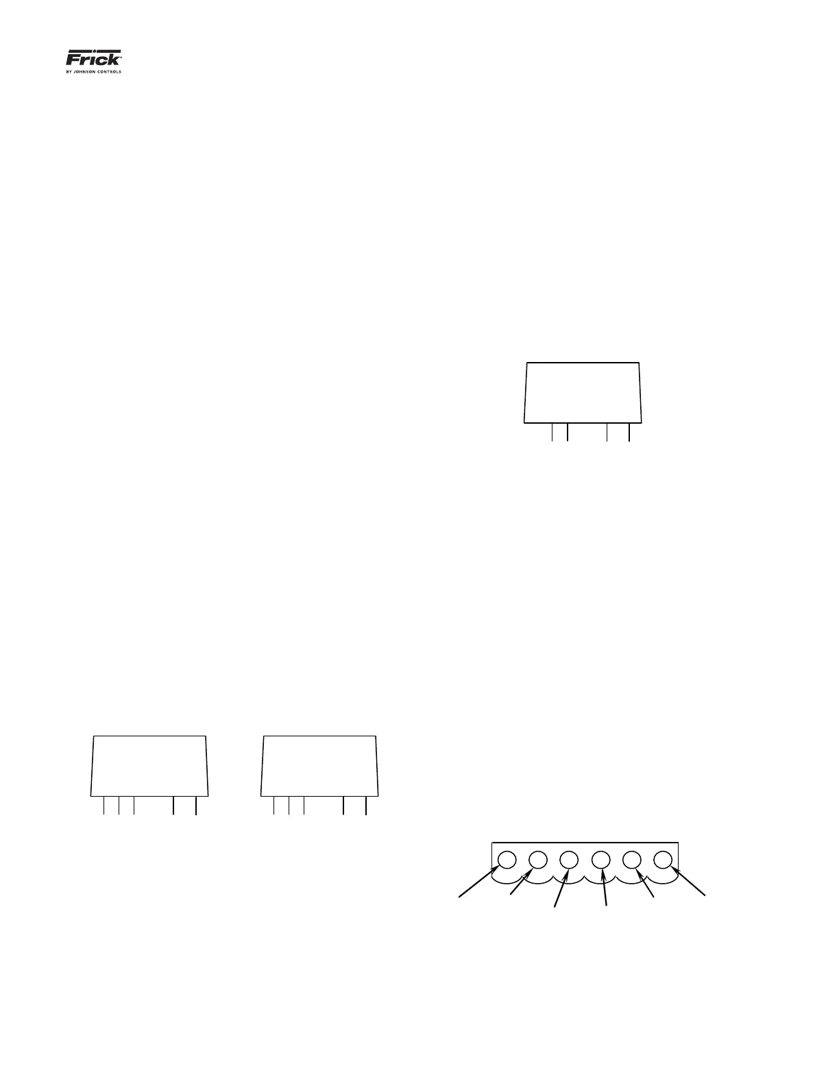
CHECKING THE DIGITAL INPUTS AND OUTPUTS
Some problems that may be encountered involve
troubleshooting the digital inputs and outputs. The
Digital I/O (Input / Output) Boards have six Digital I/O
(DIO) board connectors labeled P1 through P6. The
Input and Output modules are wired to a DIO connec-
tor plug. Position 3 provides power and position 4 is a
neutral on the DIO connectors. Positions 1, 2, 5, and 6
are signal connections, as shown below:
Position 1
Signal
Position 2
Signal
HOT NEURAL
Position 3
Signal
Position 4
Signal
The Digital board’s I/O modules are confi gured by
proper module selection, AC or DC, operating volt-
age, input or output, and moving the fuse to the in or
out position. An LED is associated with each module
and displays the state of each module. A lit LED rep-
resents an Input that is High, receiving a signal or an