QUANTUM™ HD COMPRESSOR CONTROL PANEL
MAINTENANCE
090.040-M (MAR 12)
Page 37
PHD VIBRATION ANALYSIS
The Frick™ 32 channel analog board has the built-
in capability to directly receive signals from vibration
accelerometers, and motor stator RTDs (100 Ω plati-
num) which are mounted on the compressor housing
and/or the motor/shaft. The purpose of these devices
is to monitor compressor plus motor/bearing vibra-
tion and/or motor bearing plus motor stator tem-
perature.
Accelerometers transmit continuous signals to the
analog board. The Q5 software monitors these sig-
nals, and can detect any variations in the frequency
of the vibration. If the vibration levels increase over
time, predefi ned setpoint limits may be exceeded,
resulting in a warning from the Quantum™ notifying
the operator of the condition. If the alarm is not ad-
dressed, a shutdown will occur to prevent damage to
the compressor. Likewise, if an RTD is used for bear-
ings, it will measure the temperature of the motor
bearings and stator, which may increase (due to lack
of lubrication).
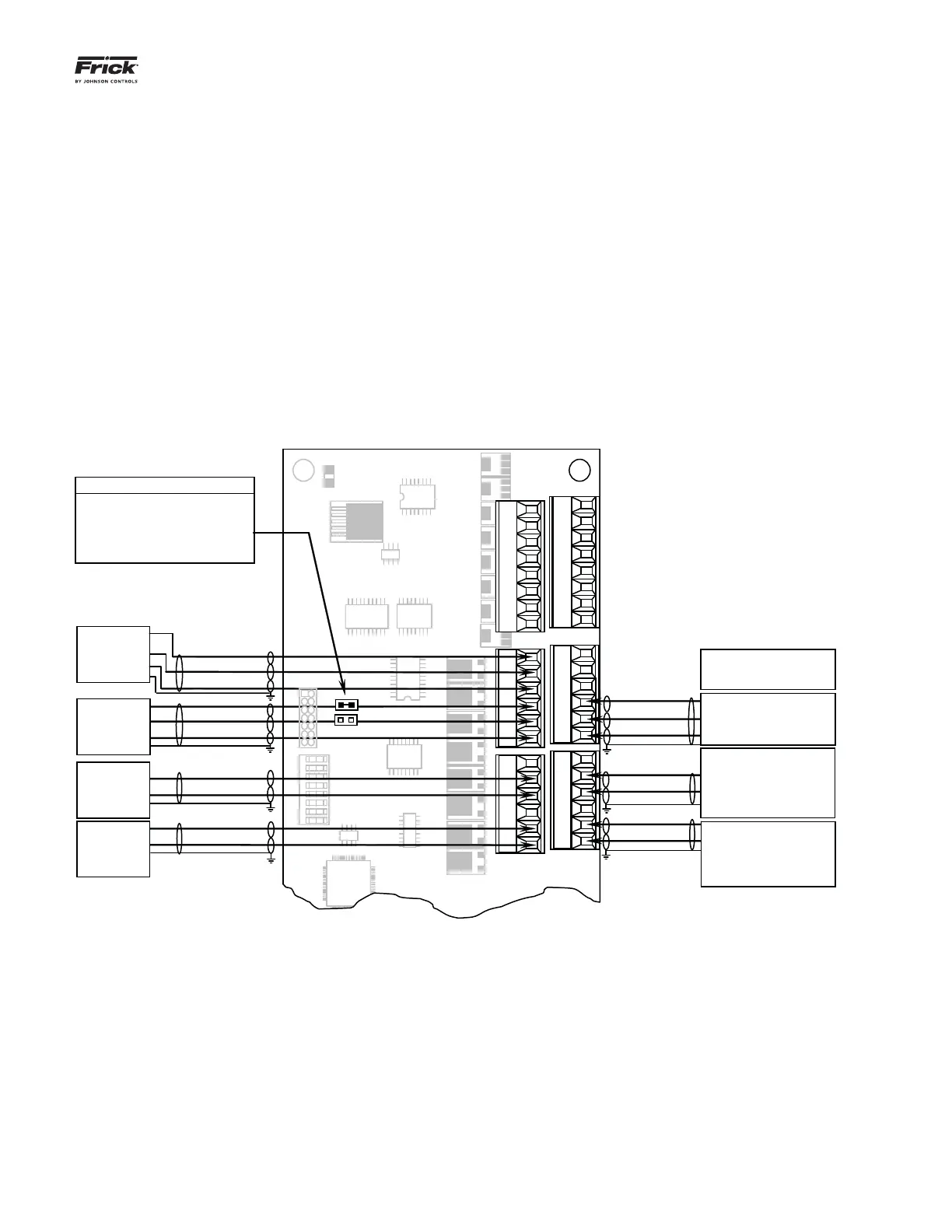
Typically, all PHD related connections will be to Ana-
log Board # 1. However, if monitoring of both motor
bearing vibration and temperature is required, the
temperature sensors will be wired to Analog board
#2, channels 19 and 20. Refer to the drawing at the
bottom of this page for the wiring connections of the
different possible confi gurations.
The full wiring diagram may be found later in this
manual in the Quantum™ Drawings section. Addi-
tional information on PHD vibration monitoring and
theory may be found in the PhD Vibration Monitoring
System manual (E70.020-TB).
Part #: 640D0168H01
P9A (Inputs)
P9B (Inputs)
1 2 3 4 5 6 7 8
U4
SW1
Open
D5
24VDC
U9
H
D Ch
.
1
Suction End
Vibration
(Accelerometer)
H
D Ch
.
2
Discharge End
Vibration
(Accelerometer)
H
D Ch
.
5
Motor Stator
#1 Temp. (RTD)
H
D Ch
.
6
Motor Stator
#2 Temp. (RTD)
Signal (to pin 1)
Minus (to pin 2)
Signal (to pin 4)
Minus (to pin 5)
Signal (to pin 5)
Plus (to pin 4)
Minus (to pin 6)
Signal (to pin 2)
Plus (to pin 1)
Minus (to pin 3)
P10A (Inputs)
P10B (Inputs)
P11B (Outputs)
P11A (Outputs)
P1
Signal (to pin 1)
Plus (to pin 1)
Signal (to pin 2)
Minus (to pin 5)
Signal (to pin 4)
Minus (to pin 2)
Minus (to pin 3)
H
D Ch
.
4
Opposite Shaft Side Motor
Vibration (Accelerometer) Or
Opposite Shaft Side Motor
Temp. (RTD or Thermocouple)
H
D Ch
.
8
Liquid Injection Oil
H
D Ch
.
3
Shaft Side Motor Vibration
(Accelerometer) Or Shaft Side
Motor Temp. (RTD or
Thermocou
le)
H
D Ch
.
Motor Stator #3 Temp. (RTD)
LK3 LK4 Gain Ratio
Out Out 1 : 1
Out * In * 11 : 1
In Out 21 : 1
In In 31 : 1
* Default
LK3
LK4
PHD Connections (Analog Board # 1)