QUANTUM™ HD COMPRESSOR CONTROL PANEL
MAINTENANCE
090.040-M (MAR 12)
Page 35
Analog Board Input Confi guration Table
Channel 0-5Vdc 1-5Vdc 4-20mA ICTD 0-20mA 0-10Vdc 2-10Vdc
POT
(Potenti-
ometer)
CT
(Motor
Current)
Accelerometer
(Vibration Moni-
toring)
RTD (Motor
Protection
Only)
1*******
2******* *
3******* *
4******* *
5******* *
6*** *** *
7*** *** *
8*** *** *
9*** *** *
10******* *
11*** *** *
12*** *** *
13*** *** *
14*** *** *
15*** *** *
16*** *** *
17 * * * * * *
18 * * * * * *
19 * * * * * *
20 * * * * * *
21 * * * * * *
22 * * * * * *
23 * * * * * *
24*** *** * *
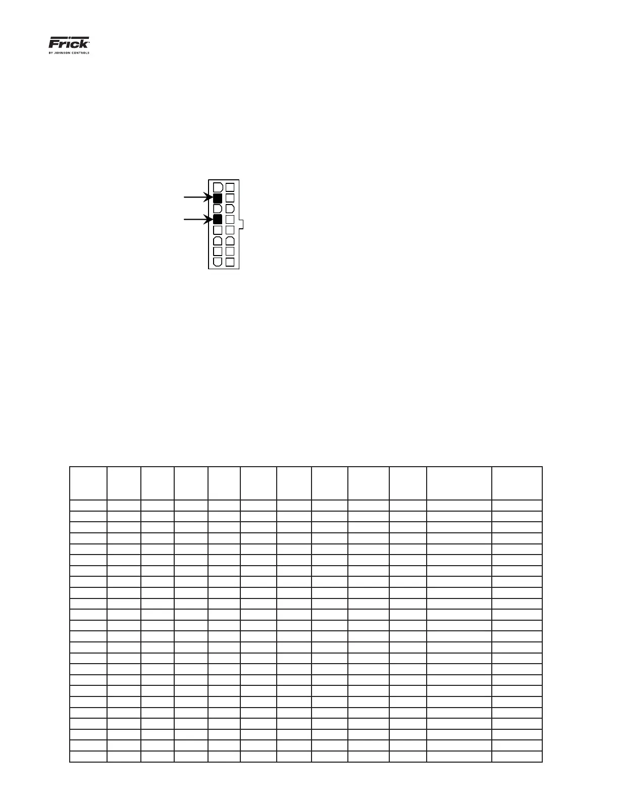
mine this is to read the voltage on a DVM (Digital
Volt Meter). This may be accomplished by locating
the white power / communications connector on the
board. Notice that the Analog Board has only one of
these connectors. The associated power/communi-
cations harness plugs in to it. Take the red (positive)
probe of the DVM and carefully insert the end into the
+12Vdc lead, and the black (negative) probe end into
the RET (Return or Common) lead, as shown below:
+12VDC
RET
Set the DVM to read DC, and set the proper range.
The Ideal voltage setting for the +12Vdc power is
+12.15 Vdc (+/- 0.05).
The cause for a low voltage reading could be:
• The power supply may need adjustment
(see the section on power supplies).
• The Power-I/O communications harness has
a problem (a new harness may be needed).
• A problem may exist with one of the I/O
boards (Digital or Analog).
• If the power LED is not lighted, check the
cable for proper connectivity.
The second power LED is D5 (+24Vdc). This +24Vdc
voltage is generated on the Analog Board from the
+12Vdc supply being fed from the Quantum™ power
supply. If the +12Vdc is present as stated earlier, then
this LED will illuminate if the on-board +24Vdc supply
is functioning properly.
ACTIVE LED
The Analog Board has an Active LED indicator that
blinks when the board’s software is running.
If the Active LED is not blinking, it could be an indi-
cation that the internal program is not running. Try
powering the Q5 controller off, then back on to see
if the Active light starts blinking. If not, a new board
may be required.
ANALOG INPUTS
An Analog Input is the portion of the hardware that
allows devices such as temperature sensors and pres-
sure transducers to interface with the Quantum™ HD.
The software program within the Quantum™ HD is
constantly looking at these Input channels, via com-
munications, and based upon what the voltage or
current level of the channel is, will provide the nec-
essary control for an associated action.
Analog inputs arrive at the board on connectors P4
through P10. Each of these connectors can receive
two channels (for a total of twenty-four).
Refer to the following chart for a listing of possible
input channel confi gurations.