EasyManua.ls Logo

Johnson Controls Hx 3 S1-THXU430W User Manual

Johnson Controls Hx 3 S1-THXU430W
78 pages
To Next Page IconTo Next Page
Page #1 background imageLoading...
Page #1 background image
Johnson Controls Ducted Systems 5407934-UIM-C-1119
Hx™3 TOUCH SCREEN THERMOSTAT
MODELS: S1-THXU430W
INSTALLATION MANUAL
11/07/18 11:14AM
º
72
Auto
COOL TO
85
62
Settings
11/07/18 11:14AM
.
LIST OF SECTIONS
GENERAL . . . . . . . . . . . . . . . . 2
SAFETY CONSIDERATIONS . 2
INSPECTION . . . . . . . . . . . . . . . . 3
LIMITATIONS . . . . . . . . . . . . . . . 3
CONVENTIONAL
COMPATIBILITY CHECK . . . . . . 3
COMMUNICATING
SYSTEM INSTALLATION . . . . 4
LOCATION . . . . . . . . . . . . . . . . . 5
MOUNTING
THE THERMOSTAT . . . . . . . . . . 5
INSTALLING A
NEW THERMOSTAT . . . . . . . . . 6
WIRING COMMUNICATION . . 8
WIRING REQUIREMENTS . . . . . 8
SYSTEM WIRING OVERVIEW . . 8
HUMIDIFIER CONNECTION . . 25
HUMIDIFICATION AND
DEHUMIDIFICATION . . . . . . . 28
INITIAL POWER-UP . . . . . . . .30
POWER-UP . . . . . . . . . . . . . . . 31
SYSTEM CONFIGURATION . . 31
SOFTWARE UPDATES . . . . . . 36
SERVICE MODE . . . . . . . . . . .37
ACCESSING SYSTEM
SETTINGS . . . . . . . . . . . . . . . . 37
SYSTEM SETTINGS . . . . . . . . 38
FAULTS AND
SYSTEM EVENTS . . . . . . . . . . 47
AIRFLOW CONFIGURATION . . 64
FORCED OPERATION . . . . . . . 65
VENTILATION SETTINGS . . . . 67
RESTORE DEFAULTS . . . . . . . 68
SERVICE SETTINGS . . . . . . .70
LOG . . . . . . . . . . . . . . . . . . . . . . 70
DEALER INFORMATION . . . . . 71
STATUS . . . . . . . . . . . . . . . . . . 73
WIRING DIAGRAMS . . . . . . . .74

Table of Contents

Question and Answer IconNeed help?

Do you have a question about the Johnson Controls Hx 3 S1-THXU430W and is the answer not in the manual?

Johnson Controls Hx 3 S1-THXU430W Specifications

General IconGeneral
BrandJohnson Controls
ModelHx 3 S1-THXU430W
CategoryThermostat
LanguageEnglish

Summary

General

Safety Considerations

Understand and pay particular attention to signal words DANGER, WARNING, and CAUTION.

Inspection

Limitations

Conventional Compatibility Check

Communicating System Installation

Location

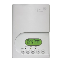
Install thermostat at or around 5 ft above the floor with good circulation.

Mounting the Thermostat

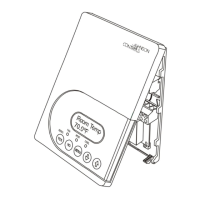
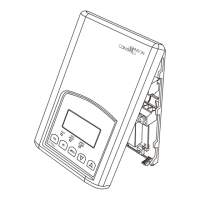
Steps for mounting the thermostat base and screen onto the wall.

Installing a New Thermostat

Step-by-step guide for installing a new thermostat base and screen.

Wiring Communication

Wiring Requirements

Use standard 18 AWG wires and keep wiring away from inductive loads.

System Wiring Overview

Explains the four wires required for a communicating system.

Thermostat Wiring

Outdoor Control Wiring

Communicating Non-Variable Capacity Models

Using a Communicating Wiring Harness

Procedure for using the S1-02542694000 communicating wiring harness.

Control Wiring: Non-Variable Capacity Outdoor Models

Control Wiring: Variable Capacity Outdoor Models

Variable Capacity Models

Indoor Control Wiring

Humidifier Connection

Bypass Humidifier

Wiring diagram for furnace and bypass humidifier.

Fan Powered Humidifiers

Humidification and Dehumidification

Initial Power-Up

Power-Up

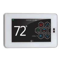
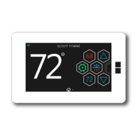
The Auto Setup screen displays on initial power-up.

System Configuration

Thermostat detects and identifies indoor and outdoor equipment.

Heat Kit Configuration

Software Updates

Restore Defaults

How to restore the thermostat to its factory default settings.

Service Mode

Accessing System Settings

How to access system settings by tapping and holding the Service icon.

System Settings

Demand Response

Setting to control thermostat operation during demand response signals.

System Settings Overview

Introduces tables detailing general system settings.

Faults and System Events

Airflow Configuration

Forced Operation

Ventilation Settings

Restore Defaults

Service Settings

Log

View event and fault logs, and check occurrence details.

Dealer Information

Status

Wiring Diagrams

Related product manuals