5407934-UIM-C-1119
Johnson Controls Ducted Systems 9
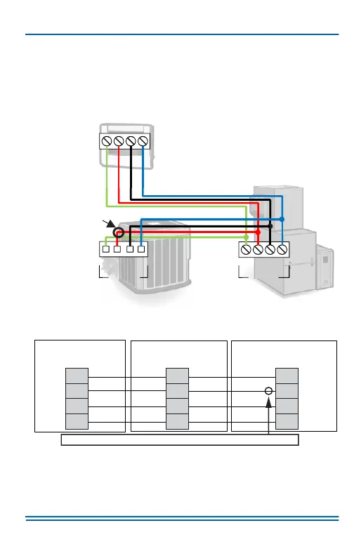
The system is connected by four wires. Two of the wires are used to
bring power to the individual controls (R and C), and two of the wires are
used for serial communication (A+ and B-).
Variable capacity outdoor units only require three wires. Variable capac-
ity equipment has its own transformer, so it does not require an R con-
nection between the indoor and outdoor equipment.
FIGURE 3: High-Level Wiring Path
FIGURE 4: Wiring Diagram - Fully Communicating System Components
Z
KDDKDD
$*5((1:,5(
55(':,5(
&%/$&.:,5(
%%/8(:+,7(:,5(
$5&%
$5&%
$5&%
287'22581,7
,1'22581,7
$
'2127
FRQQHFWWR
YDULDEOHFDSDFLW\
RXWGRRUHTXLSPHQW
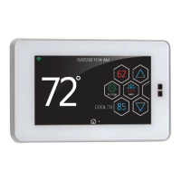
Touch Screen
Communicating
Control
VS Air Handler/Furnace
Communicating
Control
Air Conditioner/Heat Pump
Communicating
Control
A+
R
GND
B-
A+
R
C
B-
A+
R
C
B-
A0611-002
DO NOT connect to variable capacity outdoor equipment.
 Loading...